Control system for a functional section of a paper processing device

Active Publication Date: 2019-07-11
BOBST GRENCHEN
View PDF0 Cites 2 Cited by
  • Summary
  • Abstract
  • Description
  • Claims
  • Application Information

AI Technical Summary

Benefits of technology

[0014]Using the system according to the invention, it is decided on the basis of captured image data of safety-monitoring cameras (by the user himself or by a safety device described below), whether operation, more particularly remote operation, of a functional section with an operating unit is or is not acceptable for reasons of safety. Thus, safety for users and also for the processing process is increased.
[0015]The safety device analyses and appraises the captured image data. On the basis of the captured image data the safety device blocks the operating unit or gives it clearance. Based on the image data, if the safety device for example identifies a person in the functional section, the safety device blocks the operating unit. This means that, for example, any activation of the processing process in the functional section by the operating unit is impossible. If the operating unit is located at a distance from the functional section, any remote control of the functional section is thereby prevented. Alternatively, on the basis of the image data, the safety device can identify whether the safety-monitoring cameras are working correctly. If the safety device detects that the safety-monitoring cameras are not working correctly, the safety device blocks the operating unit likewise, in order to prevent overhasty and unnecessary termination of the process in the functional section.

Problems solved by technology

More especially in cases where sequences are highly complex and where multiple maintenance teams are at work, agreements that are made may frequently be poor, so the production line is stopped without reason or is brought into operation, although operation has not yet been cleared for safety reasons.

Method used


Image

  • Control system for a functional section of a paper processing device
  • Control system for a functional section of a paper processing device

Examples


Embodiment Construction

[0036]The same or similar components in different figures are given the same reference signs. The representations in the figures are schematic.

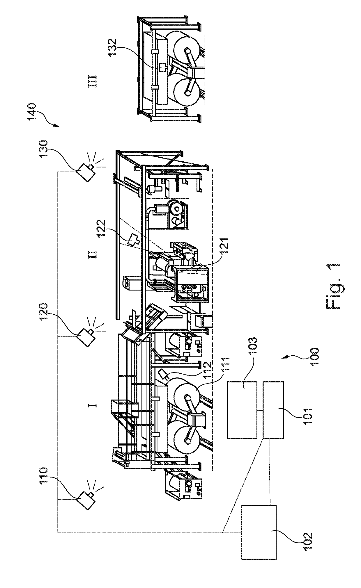
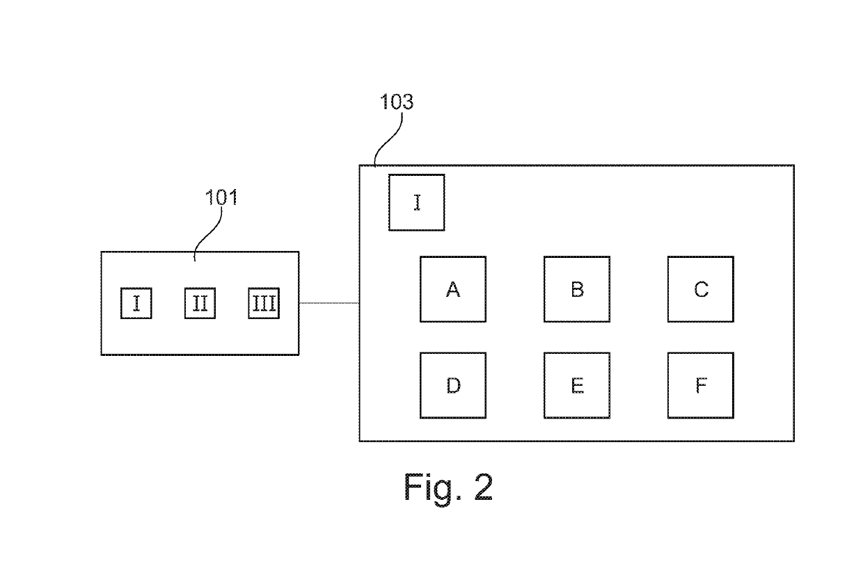
[0037]FIG. 1 shows a control system 100 for a functional section I, II, III of a paper processing device 140. The control system 100 has at least one safety-monitoring camera 110, 120, 130, which is disposed in the functional section I, II, III, such that a functional region of the functional section I, II, III can be captured by means of the safety-monitoring camera 110, 120, 130. An operating unit 101 of the system 100 is designed to operate the functional section I, II, III. The image data of the at least one safety-monitoring camera 110, 120, 130 can be selected with the operating unit 101. A display unit 103 is configured to display the selected image data, such that a user allows or blocks the operation of the functional section I, II, III on the basis of the displayed image data.

[0038]Moreover, a safety device 102 can be provided, whic...


PUM


Abstract

A control system (100) for a functional section (I, II, III) of a paper processing device (140). The control system (100) has at least one safety-monitoring camera (110, 120, 130) which is arranged in the functional section (I, II, III) such that a functional region of the functional section (I, II, III) can be captured by the safety-monitoring camera (110, 120, 130). An operating unit (101) of the system (100) is designed to operate the functional section (I, II, III), and image data of the at least one safety-monitoring camera (110, 120, 130) can be selected by the operating unit (101). A display unit (103) is configured to display the selected image data such that a user allows or blocks the operation of the functional section (I, II, III) based on the displayed image data. A safety device (102) is coupled to the safety-monitoring camera (110, 120, 130) and the operating unit (101), and the safety device (102) receives image data of the safety-monitoring camera (110,120, 130). The safety device (102) is configured such that the safety device (102) allows or blocks the operation of the functional section (I, II, III) by means of the operating unit (101) on the basis of the received image data of the safety-monitoring camera (110, 120, 130).

Description

CROSS-REFERENCE TO RELATED APPLICATIONS[0001]The present application is a 35 U.S.C. §§ 371 national phase conversion of PCT / EP2017 / 025113, filed May 9, 2017, which claims priority of German Patent Application No. 10 2016 109 128.6, filed May 18, 2016, the contents of which are incorporated by reference herein. The PCT International Application was published in the German language.TECHNICAL FIELD[0002]The invention relates to a control system for a functional section of a paper processing device.BACKGROUND OF THE INVENTION[0003]Modern production processes in the paper-processing industry, more particularly on multi-stage production lines in the paper-processing industry, are frequently monitored remotely and controlled from distant places. In this connection it is necessary to agree to the maintenance phases precisely with e.g. the maintenance staff, in order to prevent e.g. the production line from being started up, although maintenance staff are still in safety-related areas. More ...

Claims


Application Information

Patent Timeline
Patent Type & Authority Applications(United States)
IPC IPC(8): D21G5/00G05B9/02F16P3/14
CPCD21G5/00F16P3/142G05B9/02G05B2219/50198G05B19/042G05B2219/2651G05B19/4061G05B2219/37631G05B2219/40202G05B2219/40197
Inventor WICK, STEFAN
Owner BOBST GRENCHEN
Why Eureka
Try Eureka