Twisted wire manufacturing apparatus and twisted wire manufacturing method

a manufacturing apparatus and technology of twisted wire, applied in the manufacture of electrical devices, cable/conductor components, basic electric elements, etc., can solve the problems of difficulty in improving workability, trouble, and the end of electric wires, so as to reduce the burden on the operator, prevent a large tension, and reduce the height of the apparatus.

Active Publication Date: 2019-07-11
YAZAKI CORP
View PDF0 Cites 3 Cited by
  • Summary
  • Abstract
  • Description
  • Claims
  • Application Information

AI Technical Summary

Benefits of technology

[0032]According to the fourth aspect of the invention, relating to the above item (4), since a space required for manufacturing the twisted wire is secured in the vertical direction, a space required in the horizontal direction can be significantly reduced as compared to conventional examples. Moreover, since an operator does not need to move from one end to the other end of the electric wires, the burden on the operator can be reduced. Further, since the raising / lowering speed of the electric wires can be changed, for example, if the raising / lowering speed is switched from the high speed to the low speed before reaching the position of the desired lifting height, or if the raising / lowering speed is maintained at the low speed until the position of the desired lifting height, it is possible to prevent a large tension from being abruptly generated to the electric wires. As a result, it is possible to prevent troubles such as detachment of the ends of the electric wires from the members holding the ends of the electric wires. Further, by hanging and lifting the intermediate portion of the electric wires to the electric wire hanging portion, the electric wires are bent in a U shape, and both ends of the electric wires can be arranged at a position close to the operator. Therefore, the height of the apparatus can be reduced and the installation space of the apparatus can be further reduced as compared to a case where the electric wires are not bent in such a manner. Therefore, the twisted wire manufacturing apparatus according to the present configuration is capable of reducing the installation space and improving the workability without causing excessive tension in the electric wire.

Problems solved by technology

Moreover, in the above-described related technique, an operator moves from one end to the other end of the electric wires 101 so as to hold both ends of the electric wires 101 in the holding portion and the rotational holding portion, which makes it difficult to improve workability.
However, in a case where a large tension is applied to the electric wires 101 upon movement of the member on the other end side, there is a risk of trouble such that the ends of the electric wires 101 may be detached from the members holding the ends of the electric wires 101.

Method used


Image

  • Twisted wire manufacturing apparatus and twisted wire manufacturing method
  • Twisted wire manufacturing apparatus and twisted wire manufacturing method
  • Twisted wire manufacturing apparatus and twisted wire manufacturing method

Examples


embodiments

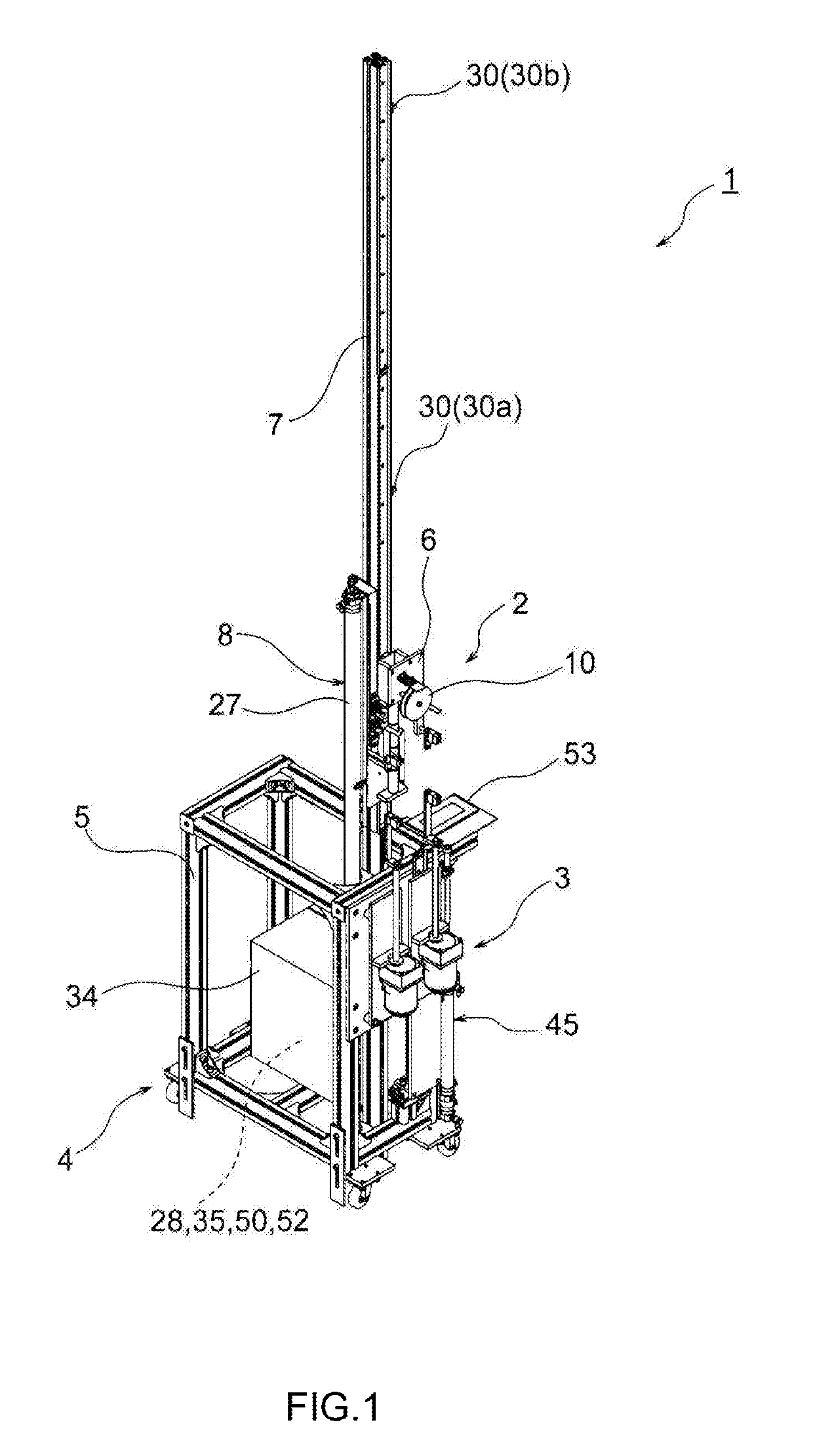
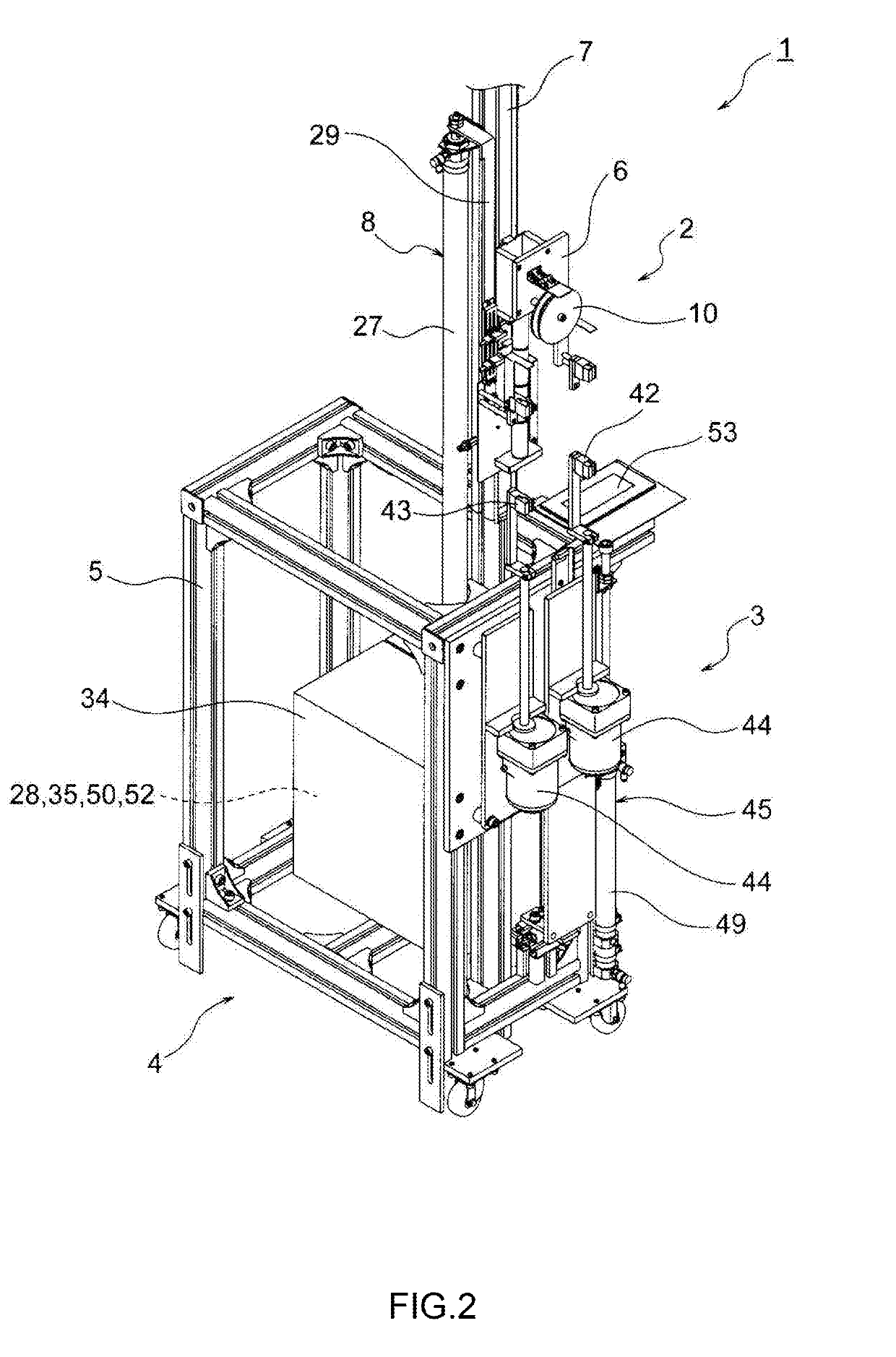
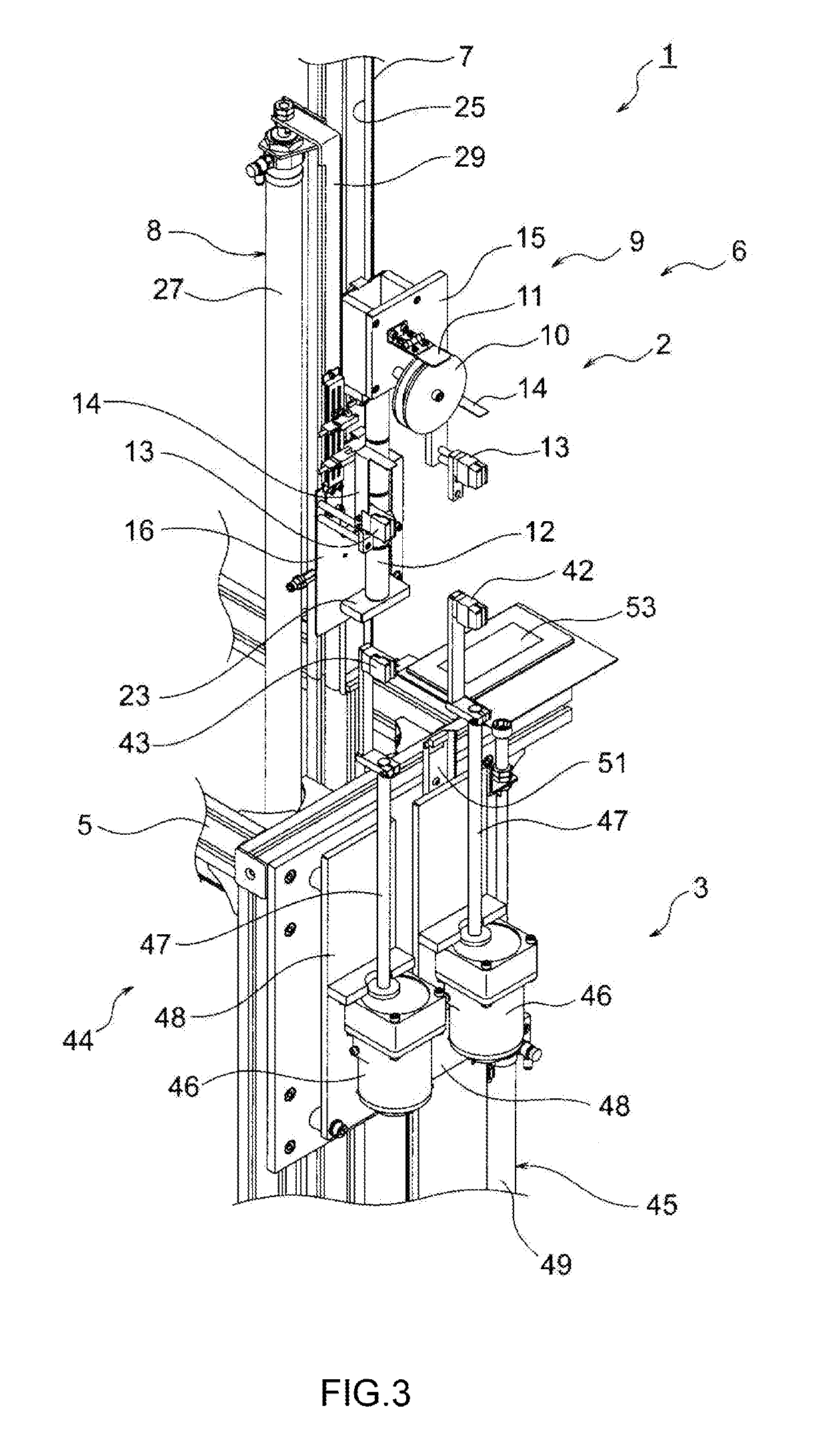
[0055]Embodiments will be described below with reference to the drawings. FIG. 1 is a perspective view of a twisted wire manufacturing apparatus according to an embodiment of the present invention. FIG. 2 is an enlarged view of a lower portion in the twisted wire manufacturing apparatus of FIG. 1, FIG. 3 is an enlarged view of a main part of FIG. 2, FIG. 4 is an enlarged view of the electric wire raising / lowering unit of FIG. 3, FIG. 5 is an enlarged view of the electric wire twisting unit of FIG. 3, FIG. 6 is an enlarged view of a sensor portion and a light-shielding portion in the electric wire raising / lowering unit of FIG. 1, FIG. 7 is a perspective view of the sensor portion of FIG. 6, and FIG. 8 is an explanatory diagram relating to operation of the electric wire raising / lowering unit of FIG. 1. FIGS. 9A to 15B are explanatory views relating to each step of a twisted wire manufacturing method (in a case of a long twisted wire) according to the embodiment of the present inventio...


PUM

PropertyMeasurementUnit
speedaaaaaaaaaa
lifting heightaaaaaaaaaa
heightaaaaaaaaaa

Abstract

An apparatus (1) is designed to manufacture a twisted wire by twisting a plurality of electric wires (101), and includes an raising and lowering unit (2), an twisting unit (3), and a control unit (4). The raising and lowering unit lifts the plurality of electric wires and lowers the manufactured twisted wire, and includes: a raising and lowering portion (6); a guiding portion (7) vertically guiding the raising and lowering portion; and a raising and lowering mechanism (8) capable of switching a raising and lowering speed of the raising and lowering portion to a high speed or a low speed.

Description

CROSS-REFERENCE TO RELATED APPLICATIONS[0001]This is a continuation of International Application No. PCT / JP2017 / 033680 filed on Sep. 19, 2017, and claims priority from Japanese Patent Application No. 2016-182672 filed on Sep. 20, 2016, the entire content of which is incorporated herein by reference.BACKGROUNDField of the Invention[0002]The present invention relates to a twisted wire manufacturing apparatus and a twisted wire manufacturing method for manufacturing a twisted wire by twisting a plurality of electric wires.Description of Related Art[0003]For example, in order to electrically connect devices mounted on an automobile, an electric wire harness is wired in a vehicle. The electric wire harness generally includes a plurality of sub-harnesses. The electric wire harness having such configuration is manufactured by combining the sub-harnesses so as to fit a desired circuit pattern. Examples of an electric wire constituting the sub-harnesses includes a twisted pair wire (twisted ...

Claims


Application Information

Patent Timeline
Patent Type & Authority Applications(United States)
IPC IPC(8): H01B13/02
CPCH01B13/02H01B13/0207
Inventor MABUCHI, MIYOSHITSUKIJI, NOBUTO
Owner YAZAKI CORP
Why Eureka
Try Eureka