Rope maintenance system

a maintenance system and rope technology, applied in the field of systems and methods, can solve the problems of increasing the cost of operators in downtime, completing the whole process, and affecting the operation, so as to achieve the effect of enhancing grip and facilitating identification of defects

Active Publication Date: 2019-07-18
DELMAR SYST
View PDF0 Cites 9 Cited by
  • Summary
  • Abstract
  • Description
  • Claims
  • Application Information

AI Technical Summary

Benefits of technology

[0059]Preferably, the crane rope spooling system further comprises a non-destructive testing unit for testing the crane rope as it is being removed from a crane drum by passing the crane rope through the non-destructive testing unit. Optionally the rope passes through a separate non-destructive testing (NDT) system, optionally disposed between the tensioning system and the reel drive system. Optionally the NDT system is contained within the tensioning system. Optionally the NDT system is disposed between the primary back tensioner and the secondary back tensioner. Optionally the rope is tested as it is being extracted from the drum of the crane. An advantage of positioning the NDT between the pr...

Problems solved by technology

The ropes are frequently changed out at the same time at significant cost to the operators.
Depending on the length of the crane's wire rope, completion of the whole process can take days or weeks, increasing the cost to the operator in downtime.
However, this is not sufficient to wind the rope W1 tightly, to the rope manufacturer's recommended tension, back onto the winch/crane drum (not shown) from the drum of the reel drive system R1, once the rope W1 has been tested by the NDT inspection unit.
This increases the risk of corrosion and failure of the rope W1.
In addition, the cost and time required to perform this operation is substantial.
A disadvantage of using capstan winch C1 is that the drum of the capstan winch C1 is flat and therefore as rope W1 is laid onto the winch, the lower layers get crushed under the weight and ten...

Method used


Image

  • Rope maintenance system
  • Rope maintenance system
  • Rope maintenance system

Examples


Embodiment Construction

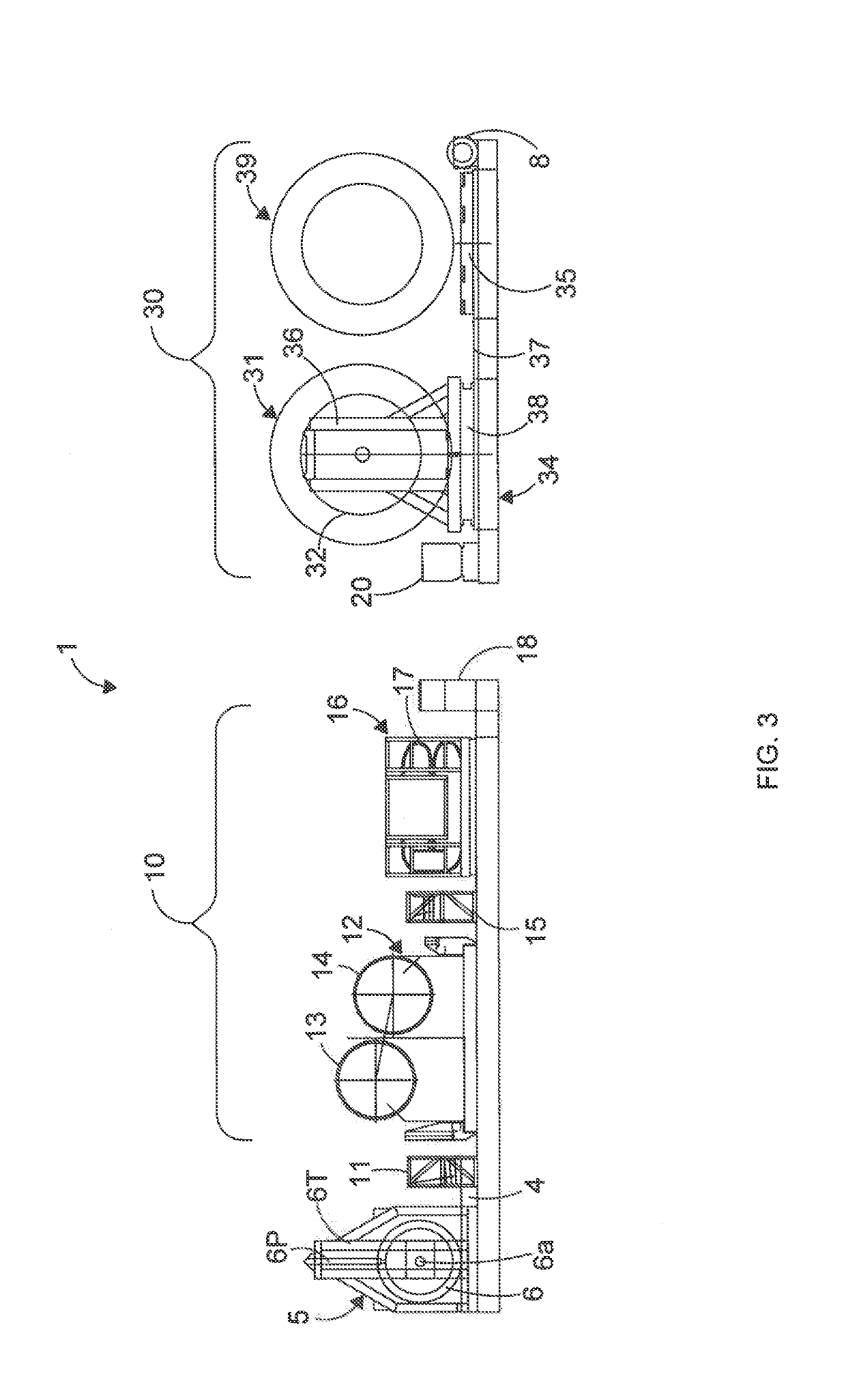
[0088]Referring now to the drawings, FIG. 3 shows an example of a crane rope spooling system 1 for spooling crane ropes on to a crane drum (not shown). The system 1 as shown in FIG. 3 comprises, from left to right: a sheave assembly 5 including a heave compensation system 6hc; a grease injector 11; a tensioning system 10 comprising at least a primary back tensioner, in this example a twin-drum traction winch 12 and a secondary back tensioner, in this example a 2-track tensioner 16 and a Non-Destructive Testing (NDT) inspection unit 15 located between the traction winch 12 and the tensioner 16; a wire guide 18; a spooling unit 20 and a reel drive system 30 which comprises at least one reel 31 and more preferably at least one spare reel 39 such that the reel drive system 30 preferably comprises at least two reels 31, 39 and an initiation winch 8.

[0089]Optionally the ropes to be maintained are wire ropes, optionally steel wire ropes typically used on cranes (not shown), for example shi...


PUM


Abstract

A method of spooling a crane rope (2) onto a crane drum through a crane rope spooling system (1) from a reel (31) under a predetermined back tension is described and includes the steps of:
    • unspooling the crane rope (2) from a reel (31) and passing the crane rope through a tensioning system (10) comprising a primary back tensioner (12) and a secondary back tensioner (16);
    • gripping the crane rope (2) within the secondary back tensioner (16) and thereby preloading the crane rope (2) with tension prior to the crane rope (2) passing through the primary back tensioner (12); and
    • applying a predetermined back tension to the crane rope (2) with the primary back tensioner (12) as the crane rope (2) is being spooled onto the crane drum under the predetermined back tension.
A crane rope spooling system (1) for spooling crane rope (2) onto a crane drum under a predetermined back tension is also described, said system (10) comprising a tensioning system (10) comprising at least a primary back tensioner (12) and a secondary back tensioner (16) and a reel (31).

Description

FIELD OF THE INVENTION[0001]This invention relates to a system and method of spooling a rope on to a drum. In particular, the invention relates to a system and method for spooling on crane ropes used on, for example, shipboard cranes and offshore cranes (such as platform, rig and vessel cranes). The invention further relates to a system and method suitable for non-destructive testing of wire ropes.BACKGROUND OF THE INVENTION[0002]Offshore operators are required to have at least one functional crane on offshore installations at all times. Regular testing of each crane's wire rope is necessary in order to identify corrosion and fatigue that might lead to failure of the rope. At present, crane ropes are inspected annually and tested every 5 years. The ropes are frequently changed out at the same time at significant cost to the operators. Additionally, the time it takes to get the rope off the drum of the crane and inspected or changed out can be substantial, with repeated transpooling ...

Claims


Application Information

Patent Timeline
IPC IPC(8): B66D1/50B66C13/00B65H59/22B66D1/36
CPCB66D1/50B66C13/00B65H59/22B66D1/36B65H2220/02B65H2701/35B66D1/28B66D1/505B66D1/741B66D3/006B66D1/52B66D1/60B66D2700/0108
Inventor SMITH, DEREK
Owner DELMAR SYST
Why Eureka
Try Eureka