Image forming apparatus and control method thereof

a technology of image forming apparatus and control method, which is applied in the direction of electrographic process apparatus, instruments, optics, etc., can solve the problems of uneven line width, uneven spot diameter, and inconvenient operation

Active Publication Date: 2019-07-18
CANON KK
View PDF0 Cites 1 Cited by
  • Summary
  • Abstract
  • Description
  • Claims
  • Application Information

AI Technical Summary

Benefits of technology

[0005]The present invention suppresses / prevents, in an image forming apparatus that uses an optical scanning device which has a different spot diameter depending on the position of the spot in the main scanning direction, line widths from becoming non-uniform in their respective positions in the main scanning direction.

Problems solved by technology

The scanning speed will not be constant and the spot diameter will not be uniform when an image forming lens that does not have the fθ characteristic is used.
However, even in a case in which the emission luminance of the laser light is adjusted so that the exposure amount per unit area on the surface of the drum will be constant, the line widths will not be uniform since each spot diameter will differ depending on its position in the main scanning direction.

Method used


Image

  • Image forming apparatus and control method thereof
  • Image forming apparatus and control method thereof
  • Image forming apparatus and control method thereof

Examples


first embodiment

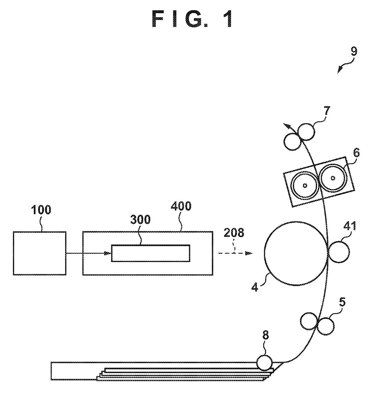
[0030]FIG. 1 is a schematic view of the arrangement of an image forming apparatus 9 according to this embodiment. A laser driving unit 300 of an optical scanning device (scanning unit) 400 emits laser light 208 based on image data output from an image signal generation unit 100. The laser light 208 scans / exposes a photosensitive member 4, which is charged by a charger unit (not shown), and forms a latent image on the surface of the photosensitive member 4. A developing unit (not shown) forms a toner image by developing the image by causing a toner (developing agent) to adhere to this latent image. A recording medium (for example, a paper sheet) fed from a sheet feeding unit 8 is conveyed by rollers 5 to a nip region between the photosensitive member 4 and a transfer roller 41. The transfer roller 41 transfers the toner image formed on the photosensitive member 4 onto the conveyed recording medium. The recording medium is subsequently conveyed to a fixing unit 6. The fixing unit 6 fi...

second embodiment

[0079]In the first embodiment, the PWM value was controlled in the manner shown in FIG. 7 in accordance with the input image data. In contrast, in the second embodiment, for example, letting PWM be the PWM value used in the first embodiment, a PWM value is controlled to be PWM×400 dpi / 600 dpi=PWM×2 / 3. For example, the second embodiment is different from the first embodiment in the point that while “255” is the PWM value at the highest image tone (that is, level 31) in the pulse signal table according to the first embodiment, “170” is the PWM value at level 31 according to the second embodiment.

[0080]In this embodiment, emission and non-emission are repeated at a constant ratio for each pixel. More specifically, based on the above-described control contents, emission and non-emission are repeated for each pixel at the ratio of

emission time: non-emission time=170: (255−170)=2:1

As a result, an amount of light of for one pixel at the highest image tone will be a value corresponding to “...

third embodiment

[0087]An embodiment which has a function that switches a PWM value in accordance with an image resolution in a sub-scanning direction will be described as the third embodiment. That is, an image forming apparatus has an arrangement in which it is possible to perform image forming by a plurality of modes that switches the image resolution in the sub-scanning direction and is capable of switching the PWM value at the time of the switching. Note a detailed description of the same components as those in the first and second embodiments will be omitted.

[0088][Processing Procedure]

[0089]FIG. 17 is a flowchart showing PWM value switching processing according to this embodiment. Since this processing procedure is cooperatively controlled by a plurality of processing units, an image forming apparatus 9 will be described as the main processing entity here.

[0090]Upon acquiring image resolution information in the sub-scanning direction from a user via a printer driver (not shown), the image for...


PUM


Abstract

An image forming apparatus comprises: a photosensitive member; a charger unit configured to charge the photosensitive member; an exposing unit configured to form a latent image by scanning the photosensitive member by laser light which has a different spot diameter in accordance with a scanning position of the photosensitive member in a main scanning direction; a developing unit configured to develop an image by adhering a toner to the photosensitive member on which the latent image is formed; and a control unit configured to control a luminance of the laser light and a resolution of the photosensitive member in a sub-scanning direction in accordance with the scanning position of the photosensitive member in the main scanning direction.

Description

BACKGROUND OF THE INVENTIONField of the Invention[0001]The present invention relates to an electrophotographic image forming apparatus and a control method thereof.Description of the Related Art[0002]As an exposure method adopted by an exposing unit of an electrophotographic image forming apparatus, there is a laser exposure method. In a laser exposure method, there is used a lens for guiding a beam of laser light from a light source unit to a scanning unit and for causing the beam of the laser light, which is deflected and scanned by the scanning unit, to form an image on a photosensitive member. It is desirable for the scanning speed of the laser light that scans the surface of the photosensitive member to be constant regardless of the position of the laser light on the surface of the photosensitive member. It is also desirable for the size (to be referred to as a spot diameter hereinafter) of a spot shape which is formed on the surface of the photosensitive member to be uniform r...

Claims


Application Information

Patent Timeline
Patent Type & Authority Applications(United States)
IPC IPC(8): G03G15/043
CPCG03G15/043G03G15/0415
Inventor SHIMIZU, YUSUKEIIDA, KENICHIOSADA, HIKARUAKIZUKI, TOMOO
Owner CANON KK
Why Eureka
Try Eureka