TFT liquid crystal display driving method and TFT liquid crystal display driving module

a technology of liquid crystal display and driving module, which is applied in the direction of instruments, static indicating devices, etc., can solve the problems of reducing the energy consumption of the tft liquid crystal display driving module, and achieve the effects of improving cross talk, reducing the energy consumption of the tft liquid crystal display driving module, and low electric power consumption

Inactive Publication Date: 2005-05-19
SEIKO INSTR INC
View PDF4 Cites 2 Cited by
  • Summary
  • Abstract
  • Description
  • Claims
  • Application Information

AI Technical Summary

Benefits of technology

[0011] An object of the present invention is to provide a TFT liquid crystal display driving method having low electric power consumption compared to line inversion driving and dot inversion driving by means of improving cross talk, non-uniform brightness in a perpendicular direction, and flicker in frame inversion driving.
[0012] The present invention solves the problems described above by forming a scanning period and a pause period within one frame period, setting the pause period to be longer than the scanning period, and utilizing the fact that the extent of influence of the pause period is proportional to the difference between the value of a signal electrode waveform integrated from one selection point to the next selection point, and the value of a background portion integrated over the same period. Specifically, write scanning to the TFT liquid crystal panel is performed at a speed equal to several times a normal speed, and the pause period is formed thereafter having a length equal to several times the length of the write period. Further, by maintaining the signal electrode waveform during the pause period at a constant gray scale level, the difference between a display pattern integrated over one frame period and the value of the waveform integrated over one frame period becomes relatively small. In addition, by placing memory in a standby mode during the pause period, and by delaying an electric power source booster circuit clock, the energy consumption of a TFT liquid crystal display driving module decreases.

Problems solved by technology

In addition, by placing memory in a standby mode during the pause period, and by delaying an electric power source booster circuit clock, the energy consumption of a TFT liquid crystal display driving module decreases.

Method used


Image

  • TFT liquid crystal display driving method and TFT liquid crystal display driving module
  • TFT liquid crystal display driving method and TFT liquid crystal display driving module
  • TFT liquid crystal display driving method and TFT liquid crystal display driving module

Examples


Embodiment Construction

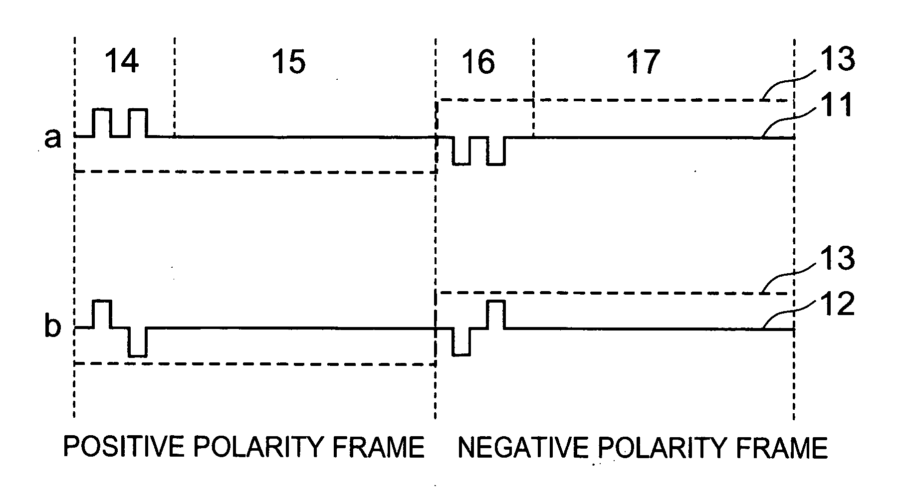
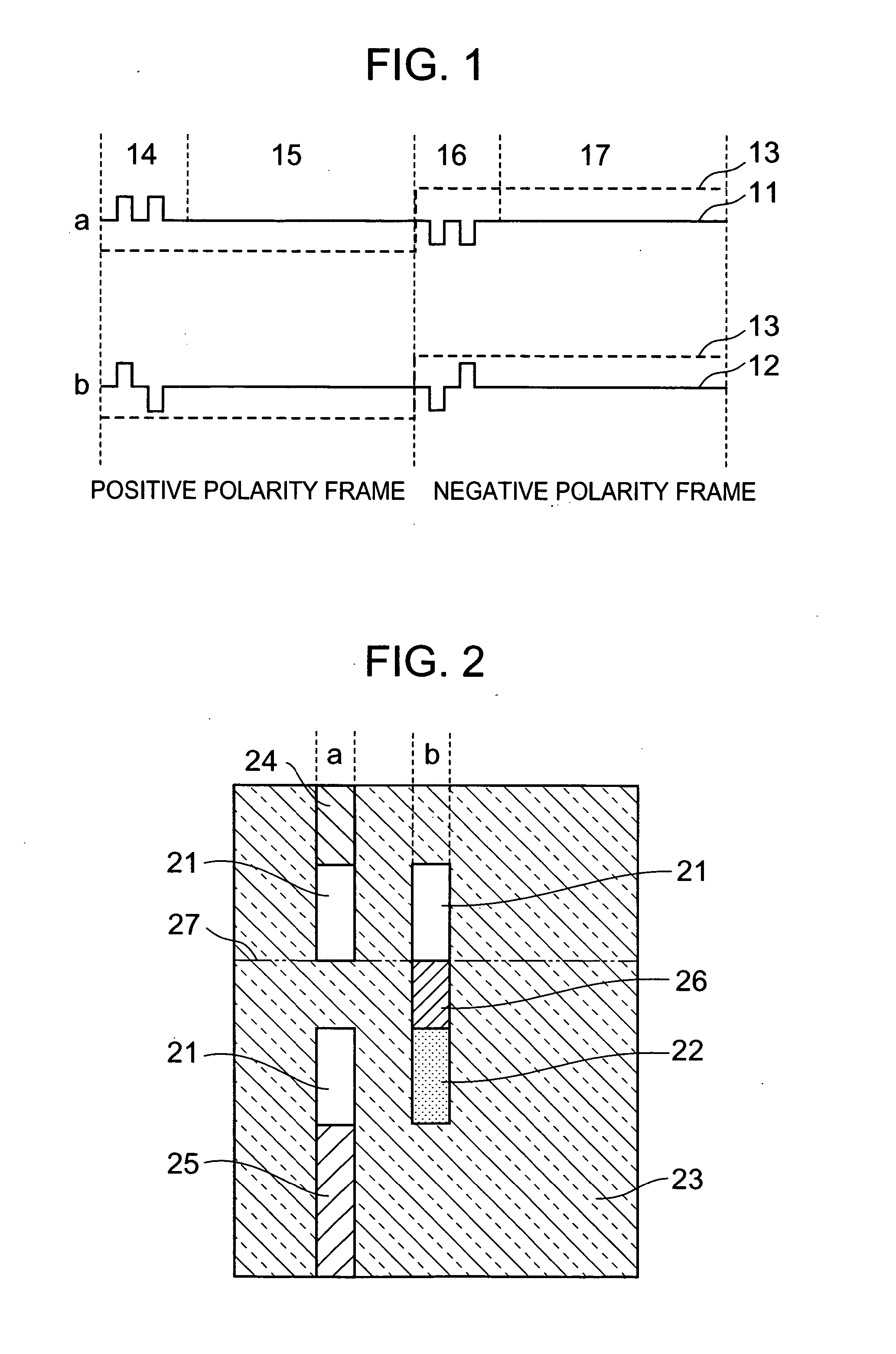
[0018]FIG. 1 shows signal electrode waveforms when-displaying a display pattern of FIG. 2 by frame driving method of the present invention.

[0019] Referring to FIG. 1, in this embodiment the display pattern is sent to a TFT liquid crystal panel by scanning during a positive polarity frame period 14, and there is a pause during a subsequent period 15 where all scanning electrodes are placed in a non-selected state. Write is performed similarly during a period 16 in a negative polarity frame, and a period 17 is formed as a pause period. The write speed here is set to four times the normal write speed, and the period 15 is set to have three times longer the time as that of the period 14. Signal electrodes in all rows are maintained at an intermediate level during the pause periods of the periods 15 and 17. A broken line 13 is a waveform that is applied to opposing electrodes. Cross talk of the portions 24, 25, and 26 of FIG. 2, non-uniformity that possess a brightness gradient in a per...


PUM

PropertyMeasurementUnit
sizeaaaaaaaaaa
polarityaaaaaaaaaa
electric potentialsaaaaaaaaaa

Abstract

To provide a TFT liquid crystal display driving method for realizing low electric power consumption compared to line inversion driving and dot inversion driving by means of improving cross talk, brightness non-uniformity in a perpendicular direction, and flicker in frame inversion driving. Write scanning to the TFT liquid crystal display is performed at a speed equal to several times a normal speed, and a pause period is formed thereafter having a length equal to several times the length of the write period. Further, by maintaining a signal electrode waveform during the pause period at a constant gray scale level, the difference between a display pattern integrated over one frame period and the value of the waveform integrated over one frame period becomes relatively small. In addition, by setting memory in a standby mode during the pause period, and by slowing an electric power source booster circuit clock, the energy consumption of a TFT liquid crystal display driving module decreases.

Description

BACKGROUND OF THE INVENTION [0001] 1. Field of the Invention [0002] The present invention relates to a TFT liquid crystal display driving method. In particular, the present invention relates to a TFT liquid crystal display driving method and to a TFT liquid crystal display driving module having low electric power consumption and little cross talk, and having a uniform brightness across the entire screen, without brightness non-uniformity. [0003] 2. Description of the Related Art [0004] Liquid crystal active matrix display devices in which thin film transistors (TFTs) and liquid crystals are laminated to display images are widely used in personal computers, workstations, and the like since a high contrast ratio display can be achieved and a multicolor display is simply made. Further, the liquid crystal active matrix display devices have also come to be used in mobile telephones in recent years due to their low electric power consumption. [0005] A TFT liquid crystal display driving me...

Claims


Application Information

Patent Timeline
Patent Type & Authority Applications(United States)
IPC IPC(8): G02F1/133G09G3/20G09G3/36
CPCG09G3/3614G09G2320/0209G09G2310/065G09G3/3648
Inventor HOSHINO, MASAFUMI
Owner SEIKO INSTR INC
Why Eureka
Try Eureka