Eureka AIR delivers breakthrough ideas for toughest innovation challenges, trusted by R&D personnel around the world.

Motor module, motor step operation control system, and motor control device

Active Publication Date: 2019-07-18
NIDEC CORP
View PDF0 Cites 0 Cited by
  • Summary
  • Abstract
  • Description
  • Claims
  • Application Information

AI Technical Summary

Benefits of technology

The present invention allows for changing the amount of displacement of a rotor per pulse, without changing the mechanical structure of the motor. This is achieved by modifying the "variable step-size information" recorded in a memory, which can be updated with a signal input or a switching operation from an external device. The technical effect is the ability to change the amount of displacement of the rotor per pulse, without making any changes to the motor's mechanical structure.

Problems solved by technology

However, as compared to e.g. brushless DC motors, stepping motors have problems such as significant vibration and noise, low efficiency of energy conversion, and loss of synchronization.

Method used


Image

  • Motor module, motor step operation control system, and  motor control device
  • Motor module, motor step operation control system, and  motor control device
  • Motor module, motor step operation control system, and  motor control device

Examples


embodiments

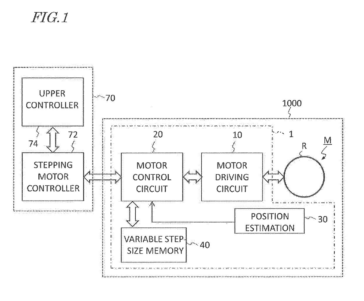
[0091]FIG. 12 is a schematic diagram showing an exemplary construction of a motor module 1000 according to an embodiment of the present disclosure.

[0092]As shown in FIG. 12, the motor module 1000 of the present embodiment includes a motor M, a detection device 150, an amplification circuit 200, a position estimation device 30, a motor control device (control circuit) 20, and a motor driving circuit (driving circuit) 10. The motor M in the present embodiment is a brushless DC motor which has a rotor R that rotates around a center axis.

[0093]From the external device (controller) 70, external signals, e.g., a pulse signal designating a rotary position of the rotor R, is input to the motor module 1000. In use, the motor module 1000 is attached to a product. The product may be a multifunction product having the functions of a printer, a scanner, a facsimile, etc., or an electric machine such as electric power steering, an antenna tilter, or a fan, for example. When used in a multifunctio...


PUM


Abstract

In one implementation, a motor module according to the present invention includes: a motor driving circuit 10 to drive a motor M; and a position estimation device 30 to output an estimated position signal of a rotor R of the motor M. It also includes: a motor control circuit 20 to supply a command voltage value to the motor driving circuit 10 in response to a pulse signal; and a variable step-size memory 40 storing variable step-size information, which defines an amount of displacement of the rotor R per pulse of the pulse signal. The estimated position signal is an analog or digital signal. Upon receiving a pulse signal, the motor control circuit 20 determines the command voltage value based on an estimated position value of the rotor R acquired from the position estimation device 30 and the variable step-size information read from the variable step-size memory 40. The motor driving circuit 10 changes the position of the rotor R based on the command voltage value.

Description

TECHNICAL FIELD[0001]The present application relates to a motor module, a motor step operation control system, and a motor control device. Moreover, the present application also relates to a device and a motor step operation control system including the motor module.BACKGROUND ART[0002]A stepping motor is able to change the position and speed of its rotor in response to a pulse signal that is input from an external device. Stepping motors are widely used in devices such as printers, scanners, copiers, and multifunction products. However, as compared to e.g. brushless DC motors, stepping motors have problems such as significant vibration and noise, low efficiency of energy conversion, and loss of synchronization.[0003]Japanese Laid-Open Patent Publication No. 2015-19563 discloses an image forming device having a brushless DC motor instead of a stepping motor. Upon receiving a pulse signal that designates the position of the rotor, the brushless DC motor in this device rotates the rot...

Claims


Application Information

Patent Timeline
IPC IPC(8): H02P8/22H02P8/08
CPCH02P8/22H02P8/08H02P6/06H02P6/17H02P8/42H02P8/14G01R23/00
Inventor FUJITA, ATSUSHIISHIGAMI, SHOTAFUKUMURA, TOMOHIRO
Owner NIDEC CORP
Why Eureka
Eureka Blog
Learn More