
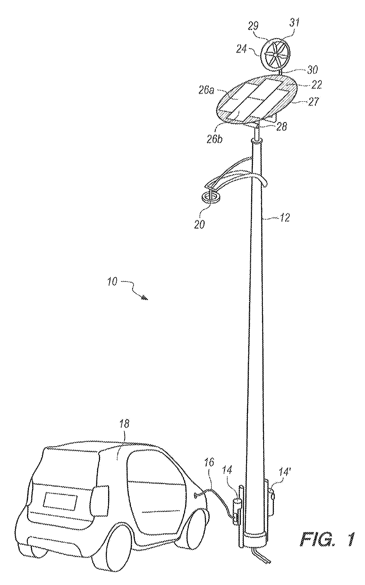
Light standard with electric vehicle (EV) charger

a technology for electric vehicles and chargers, which is applied in the direction of wind motors with parallel air flow, wind power generation, and power generation with built-in power, etc. it can solve the problems of inefficient high-power lights at night, limited lighting functions of light posts, and sized connections with the grid to supply (operate) inefficient high-power lights. , to achieve the effect of reducing the energy demand of light posts, reducing the energy consumption of light posts, and reducing the energy

Active Publication Date: 2019-07-25
BEAM GLOBAL
View PDF2 Cites 14 Cited by
  • Summary
  • Abstract
  • Description
  • Claims
  • Application Information

AI Technical Summary

Benefits of technology

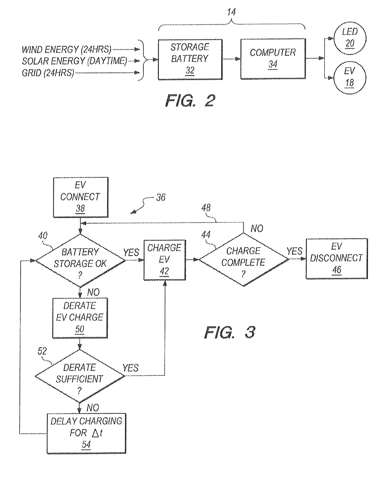
The present invention is a combination of an electric vehicle charging station and a public / private light post in a populated area. The charging station is connected to a distributed power grid and has access to excess power from the grid that is not being used. The charging station also has renewable energy resources, including a solar array and a wind turbine, to collect and generate electric energy. By monitoring and controlling the level and capabilities of the storage battery, the computer-control ensures that the charging station efficiently uses the available electric energy and always prioritizes the collection of energy from the renewable sources. The technical effect is a balanced and efficient use of electric energy by the electric vehicle charging station.

Problems solved by technology

For another, the lighting function of the light post is periodic and limited primarily to nighttime.
Moreover, connections with the grid have been sized to supply (operate) inefficient high power lights at night.

Method used


Image

  • Light standard with electric vehicle (EV) charger
  • Light standard with electric vehicle (EV) charger

Examples


Embodiment Construction

[0014]Referring initially to FIG. 1, a charging station in accordance with the present invention is shown and is generally designated 10. As shown, the charging station includes a light post 12 which is commonly used to light large areas such as streets and parking lots. As envisioned for the present invention, the light post 12 may be of any type that is well known and commonly used. Importantly, the light post 12 will typically be connected with a distributed power grid (not shown), and it will preferably be located in a populated area. The light post 12 can be either publically or privately owned. In either case, due to its connection with the distributed power grid, the electric energy that can be used by the light post 12 will be regulated.

[0015]FIG. 1 also shows that the charging station 10 includes a connector(s) 14 (14′) that is / are mounted on the light post 12. FIG. 1 also shows that the connector 14 is can be engaged, via a cable 16, with an electric vehicle 18 (hereinafte...


PUM


Abstract

A charging station for electric vehicles (EVs) is mounted on a public light post which receives an allotment of electric energy from a distributed power grid. In addition to its electrical connection with the distributed power grid, the charging station is electrically connected with a solar array on the light post that collects solar electric energy. Also mounted on the light post is a wind turbine that produces wind-generated electric energy. The electric energy from all three sources (i.e. solar, wind and grid) is consolidated in a storage battery at the charging station. The consolidated electric energy is then used for charging EVs, with an overriding priority given to electric energy allotted for regulated grid support requirements, such as street lighting and lighting for public venues.

Description

FIELD OF THE INVENTION[0001]The present invention pertains generally to stations for charging electric vehicles (EVs). More particularly, the present invention pertains to charging stations that use, in combination electric energy collected by solar energy sources, electric energy generated by wind turbines, and electric energy provided by a local distributed power grid. The present invention is particularly, but not exclusively useful as an EV charging station that uses consolidated electric energy from renewable sources (e.g. solar and wind) along with electric energy from a local distributed power grid for charging EVs; with an overriding priority given to electric energy uses for regulated grid support requirements, such as street lighting and lighting for public venues.BACKGROUND OF THE INVENTION[0002]Consumers who have large electric energy requirements, and who obtain their electric energy directly from a distributed power grid, are not always able to use the electric energy ...

Claims


Application Information

Patent Timeline
Patent Type & Authority Applications(United States)
IPC IPC(8): B60L11/18F21S8/08F21V33/00H02S40/38H02J3/38H02S20/32H02J7/35F03D9/11F03D9/25F03D9/00F03D13/20F03D1/04
CPCY02T90/12B60L53/31H02S40/38H02J3/383H02J3/386H02S20/32H02J7/35F03D9/11F03D9/25F03D9/007F03D13/20F03D1/04F21Y2115/10F21S8/086B60L53/14F21V33/00F21S9/043F21S9/035H02S10/12H02S20/10B60L53/51B60L53/52B60L53/62B60L53/63B60L2240/80Y02E10/728Y02B20/72Y02E10/56Y02E10/72Y02E10/76Y02T90/16Y02T10/70Y02T90/14Y02T10/7072Y02E60/00Y02E70/30H02J3/322Y04S30/12Y02T90/167
Inventor WHEATLEY, DESMONDSENATORE, PATRICK
Owner BEAM GLOBAL
Learn More