Kinetic Energy Generating Device

a kinetic energy and generating device technology, applied in the direction of dynamo-electric machines, structural associations, supports/encloses/casings, etc., can solve the problems of inefficient power supply of conventional small kinetic power generating devices, bulky common mechanical kinetic electric power devices, and noisy noise, so as to achieve enhanced change of magnetic flux, high power kinetic energy, and reduce magnetic leakage

Active Publication Date: 2019-07-25
SHENZHEN EBELONG TECH CO LTD
View PDF0 Cites 7 Cited by
  • Summary
  • Abstract
  • Description
  • Claims
  • Application Information

AI Technical Summary

Benefits of technology

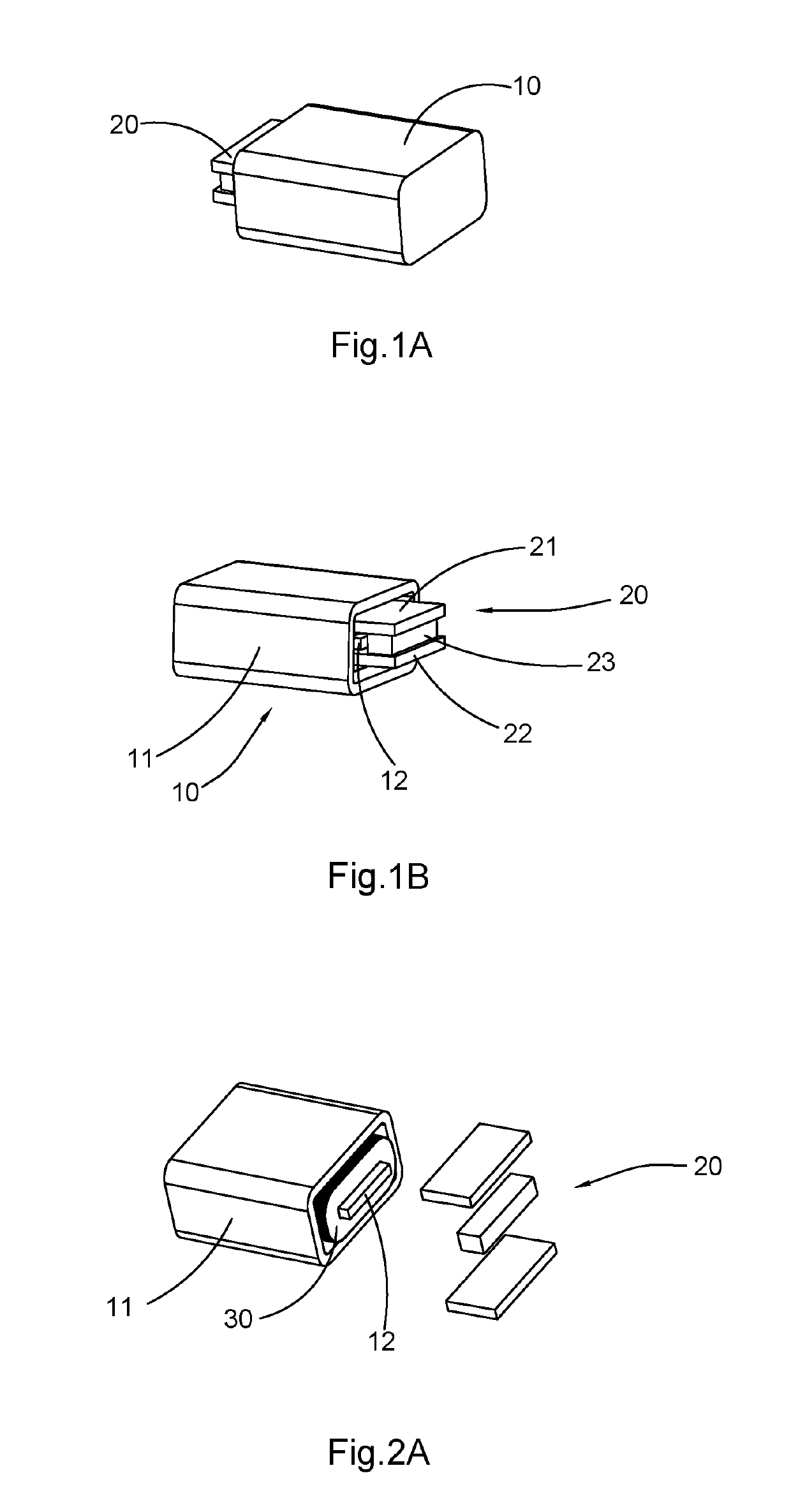
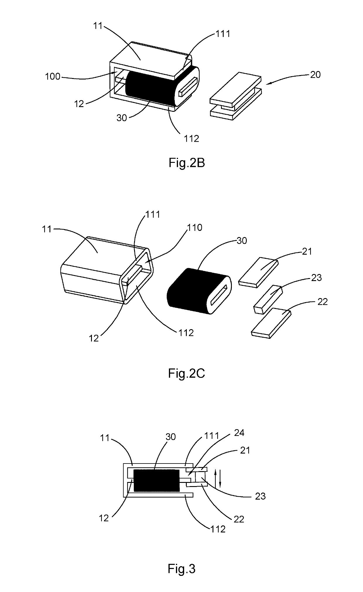
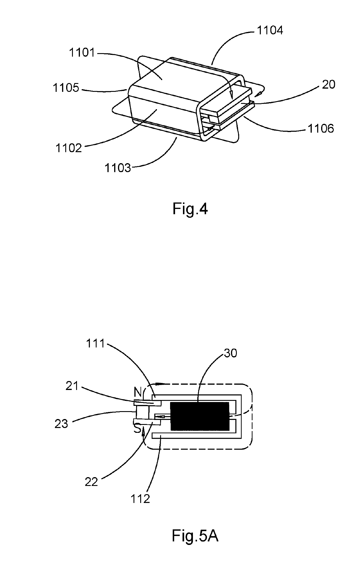
[0006]Another object of the present invention is to provide a high power kinetic energy generating device, which utilizes a magnetically permeable cavity structure and has the induction coil arranged on the middle column located in the magnetically permeable cavity, wherein the magnetic group is allowed to move up and down on a side of the magnetically permeable cavity, such that the entire coil can be completely covered by the magnetic induction lines and, therefore magnetic leakage can be reduced, which allows the coil to gain an enhanced change of magnetic flux from the movement of the magnetic group, so as to generate high powered induced current in the coil.
[0007]Another object of the present invention is to provide a high power kinetic energy generating device, which performs more efficiently in generating electricity.
[0008]Another object of the present invention is to provide a high power kinetic energy generating device, which has a magnetically permeable cavity body to reduce magnetic leakage.
[0009]Another object of the present invention is to provide a high power kinetic energy generating device, which has smaller size than regular conventional kinetic electricity generation device of the same power, provides high power electricity, and performs significantly better electromagnetic transduction, such that it has greatly enhanced industrial usability and much wider application.

Problems solved by technology

Common mechanical kinetic electric power devices are bulky, noisy, and relatively inefficient in generating electricity.
Although small low-power consumption electronic products do not require much on the power supply device, conventional small kinetic power generating devices still cannot supply power efficiently.

Method used


Image

  • Kinetic Energy Generating Device
  • Kinetic Energy Generating Device
  • Kinetic Energy Generating Device

Examples


Embodiment Construction

[0122]The following description is disclosed to enable any person skilled in the art to make and use the present invention. Preferred embodiments in the following are examples only and person skilled in the art can come out with other obvious alternatives. The general principles defined in the following description would be applied to other embodiments, alternatives, modifications, equivalents, and applications without departing from the spirit and scope of the present invention.

[0123]Those skilled in the art should understand that, in the disclosure of the present invention, terminologies of “longitudinal,”“lateral,”“upper,”“lower,”“front,”“back,”“left,”“right,”“perpendicular,”“horizontal,”“top,”“bottom,”“inner,”“outer,” and more that indicate relations of direction or position are based on the relations of direction or position shown in the appended drawings, which is only for ease of describing the present invention and simplifying the description, rather than to indicate or impl...


PUM


Abstract

A high power kinetic energy generating device comprises: a magnetic group, a magnetically permeable cavity body, and a coil. The magnetic group comprises an upper magnetically permeable member, a lower magnetically permeable member, and a permanent magnet member. A magnetic gap is defined between the upper magnetically permeable member and the lower magnetically permeable member. The magnetically permeable cavity body and the magnetic group form a magnetically permeable cavity. The magnetically permeable cavity body further comprises a middle column arranged in the magnetically permeable cavity. The coil is also arranged in the magnetically permeable cavity, and surrounds the middle column. The middle column extends into the magnetic gap. The magnetic group is displaced relatively to the middle column, so that the middle column moves into contact the upper magnetically permeable member and the lower magnetically permeable member alternately, which changes the direction of magnetic induction lines passing through the coil and therefore generates an induced current.

Description

CROSS REFERENCE OF RELATED APPLICATION[0001]This is a U.S. National Stage under 35 U.S.C. 371 of the International Application Number PCT / CN2016 / 078438, filed Apr. 5, 2016, which claims priority under 35 U.S.C. 119(a-d) to Chinese application number 2016100790220, filed Feb. 4, 2016. The afore-mentioned patent applications are hereby incorporated by reference in their entireties.NOTICE OF COPYRIGHT[0002]A portion of the disclosure of this patent document contains material which is subject to copyright protection. The copyright owner has no objection to any reproduction by anyone of the patent disclosure, as it appears in the United States Patent and Trademark Office patent files or records, but otherwise reserves all copyright rights whatsoever.BACKGROUND OF THE PRESENT INVENTIONField of Invention[0003]The present invention relates to an energy generating device, and more particularly to an energy generating device converting kinetic energy into electric power.Description of Related...

Claims


Application Information

Patent Timeline
Patent Type & Authority Applications(United States)
IPC IPC(8): H02K35/02H02K5/04H02K7/00
CPCH02K35/02H02K5/04H02K7/003H02K35/04H02K5/02H02K2213/03H02K11/0141
Inventor LIAO, SHUHUILIU, YUANFANGLIAO, WANGHONG
Owner SHENZHEN EBELONG TECH CO LTD
Why Eureka
Try Eureka