
Automatic multi-chassis link aggregation configuration with link layer discovery

a multi-chassis, link layer technology, applied in the field of computer systems, can solve the problems of relatively complicated, tedious, error-prone, etc., and achieve the effect of increasing bandwidth

Active Publication Date: 2019-07-25
SUPER MICRO COMP
View PDF5 Cites 12 Cited by
  • Summary
  • Abstract
  • Description
  • Claims
  • Application Information

AI Technical Summary

Benefits of technology

The patent describes a way for two network switches to communicate with each other using a server computer. The server computer analyzes packets from other devices and automatically assigns ports on the network switches to create a single channel of communication. This improves the efficiency of the network and reduces the need for manual setup.

Problems solved by technology

However, setting up communication ports for link aggregation is relatively complicated, tedious, and error-prone.

Method used


Image

  • Automatic multi-chassis link aggregation configuration with link layer discovery
  • Automatic multi-chassis link aggregation configuration with link layer discovery
  • Automatic multi-chassis link aggregation configuration with link layer discovery

Examples


Embodiment Construction

[0017]In the present disclosure, numerous specific details are provided, such as examples of systems, components, and methods, to provide a thorough understanding of embodiments of the invention. Persons of ordinary skill in the art will recognize, however, that the invention can be practiced without one or more of the specific details. In other instances, well-known details are not shown or described to avoid obscuring aspects of the invention.

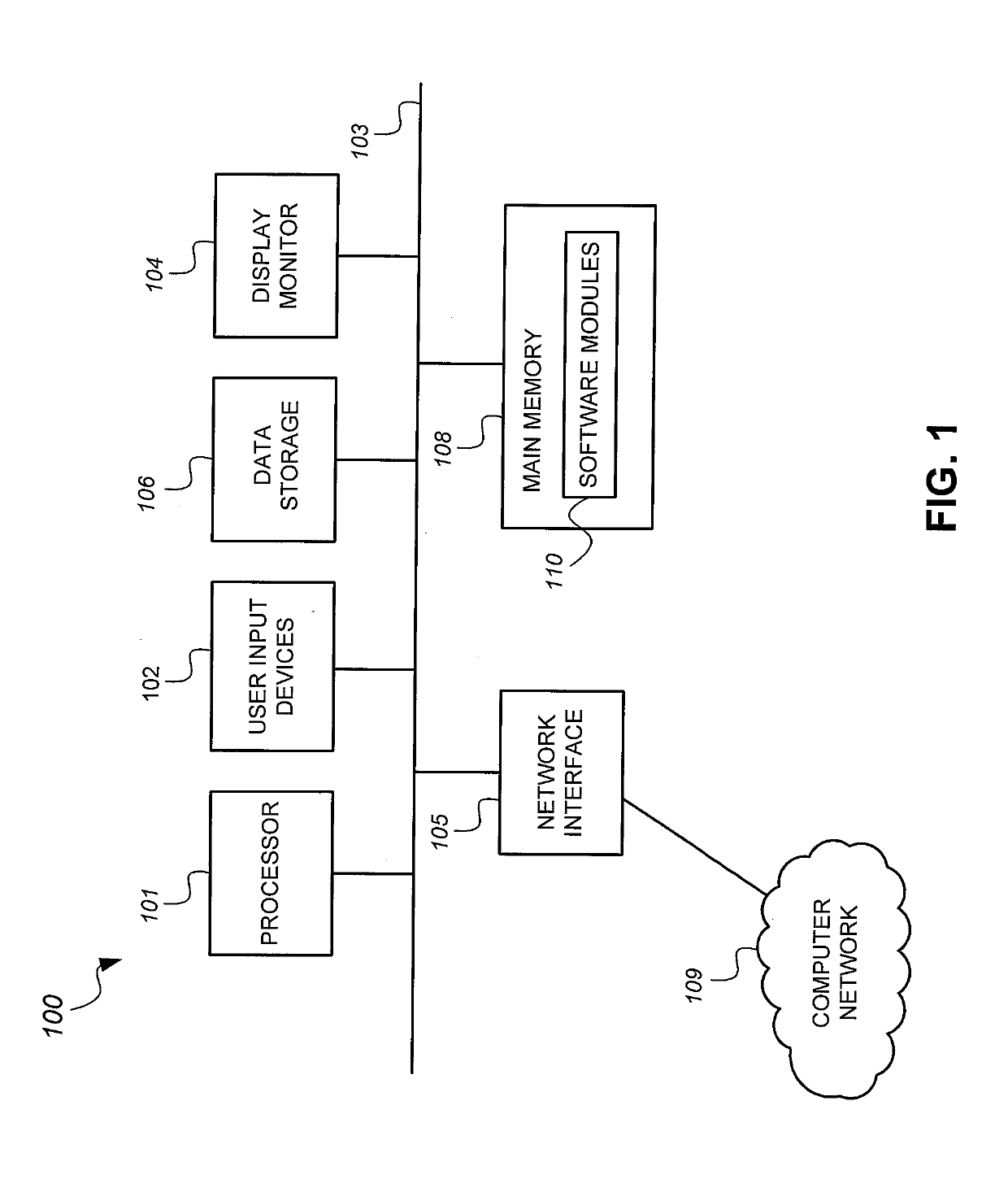
[0018]Referring now to FIG. 1, there is shown a schematic diagram of a computer system 100 that may be employed with embodiments of the present invention. The computer system 100 may be employed as a network switch or other computers described below. The computer system 100 may have fewer or more components to meet the needs of a particular application. The computer system 100 may include one or more processors 101. The computer system 100 may have one or more buses 103 coupling its various components. The computer system 100 may include one ...


PUM


Abstract

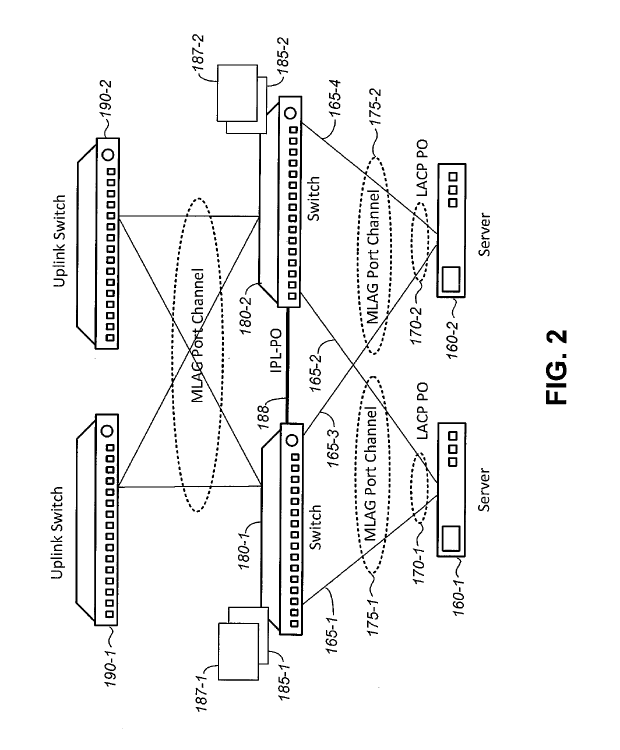
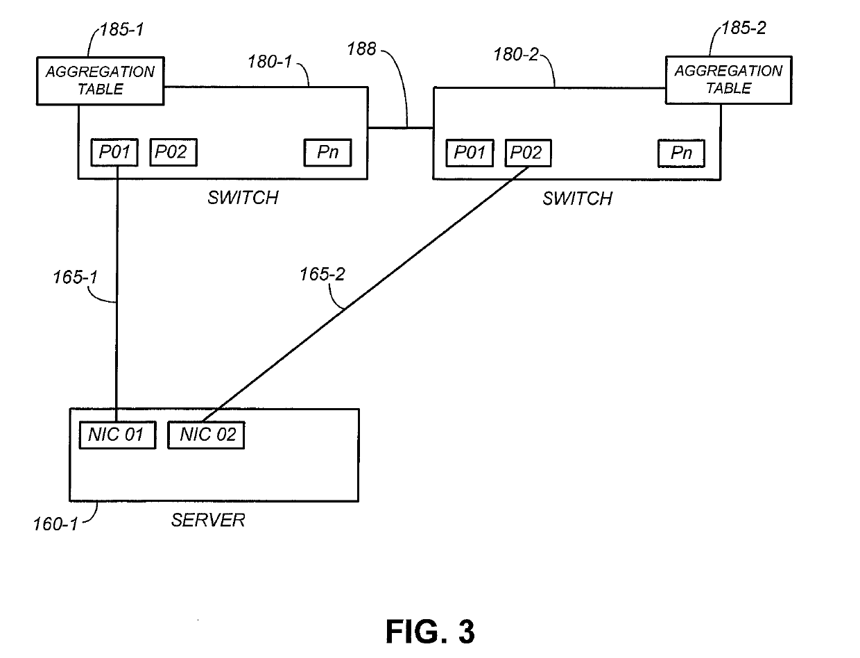
A computer network includes a server computer having communication ports that are wired to switch ports of two separate network switches. The network switches receive link layer discovery protocol (LLDP) packets from other network devices, and automatically aggregate corresponding switch ports into a port channel aggregation based on the contents of the LLDP packets.

Description

CROSS-REFERENCE TO RELATED APPLICATION[0001]This application is a continuation-in-part of U.S. application Ser. No. 15 / 875,044, filed on Jan. 19, 2018, which is incorporate herein by reference in its entirety.BACKGROUND OF THE INVENTION1. Field of the Invention[0002]The present invention relates generally to computer systems, and more particularly but not exclusively to computer networks.2. Description of the Background Art[0003]A network device, such as a server computer or a network switch, has a communication port that may be linked to a communication port of another network device. For example, a server computer may have a communication port in the form of a network interface card (NIC) port. Network switches have communication ports in the form of switch ports. The NIC port of a server computer may be linked to a switch port of a network switch to allow transmission of network traffic between the server computer and the network switch over the link. The network switch may have ...

Claims


Application Information

Patent Timeline
Patent Type & Authority Applications(United States)
IPC IPC(8): H04L12/709H04L12/24H04L45/243H04L49/111
CPCH04L45/245H04L41/12H04L41/0876H04L41/0213H04L49/15H04L49/30H04L41/046H04L41/0886Y02D30/00
Inventor JAILANI, SAHUL HAMEED ABDUL KADER
Owner SUPER MICRO COMP
Learn More