Long rod polishing device

Pending Publication Date: 2019-08-01
MAKITA CORP
View PDF4 Cites 12 Cited by
  • Summary
  • Abstract
  • Description
  • Claims
  • Application Information

AI Technical Summary

Benefits of technology

[0026]A main effect of this disclosure is to provide a long rod polishing device compact

Problems solved by technology

Since the storage battery 180 projects upward in such machine, the storage battery 180 is not compact due to the amount of pro

Method used


Image

  • Long rod polishing device
  • Long rod polishing device
  • Long rod polishing device

Examples


Example

First Embodiment

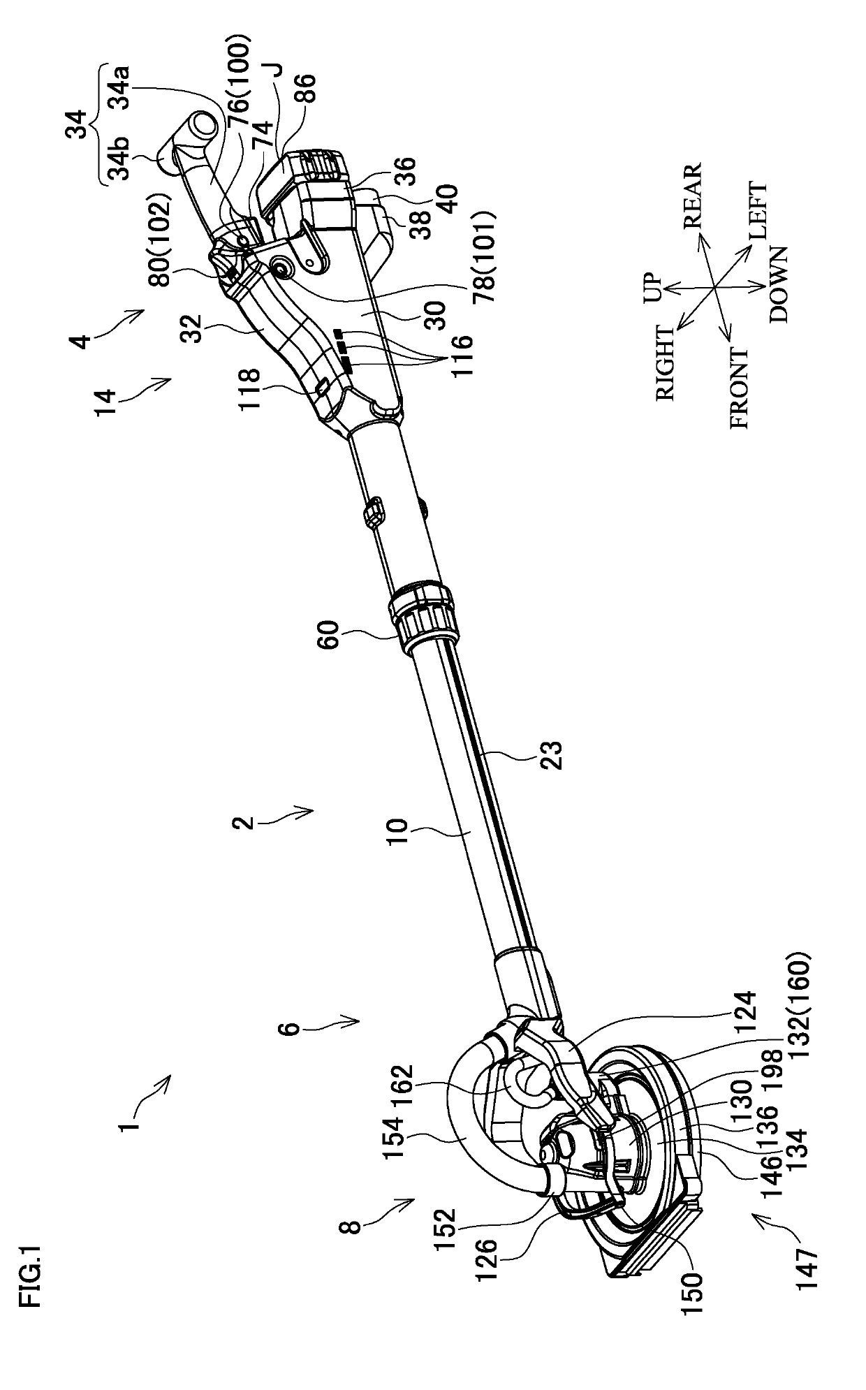
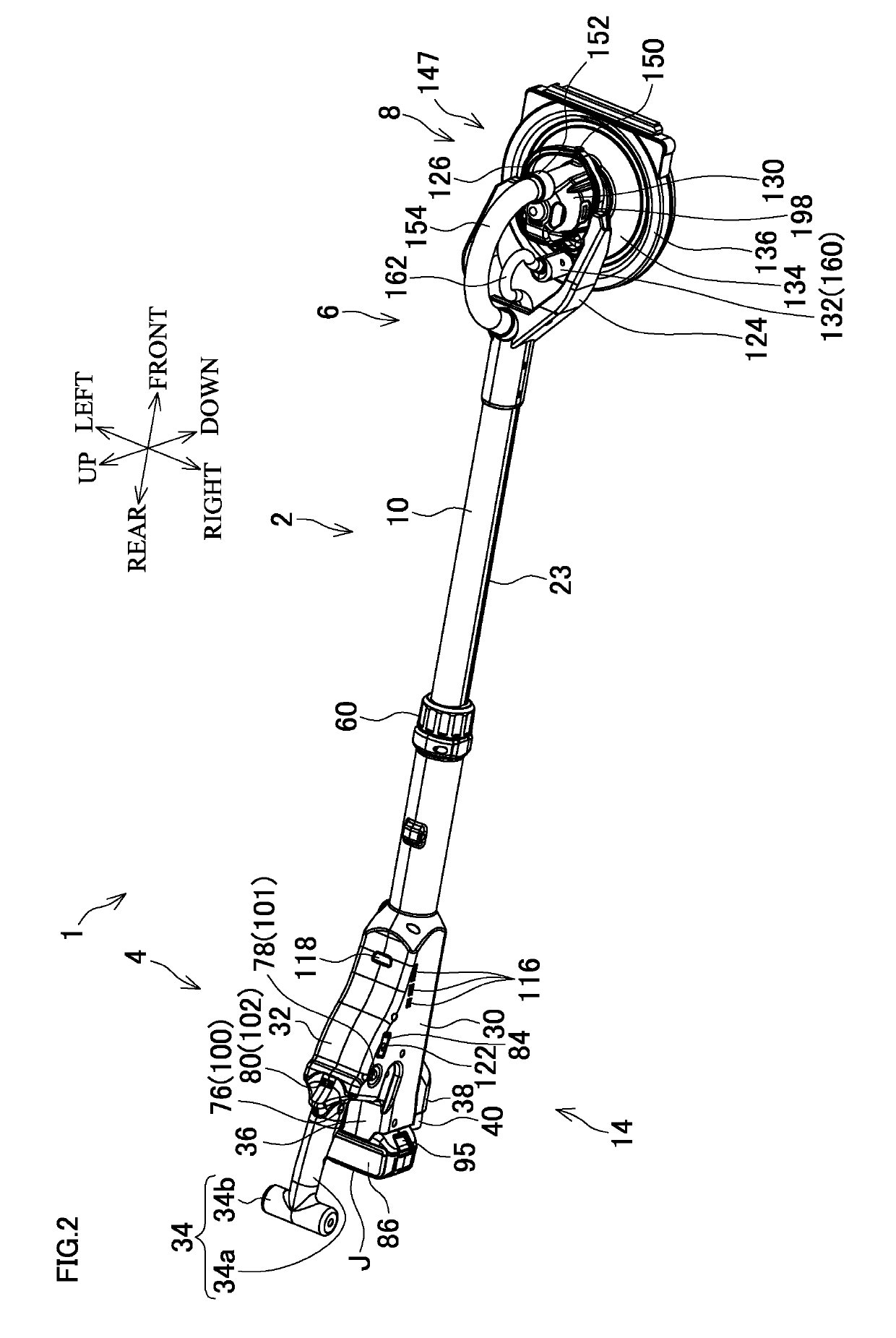
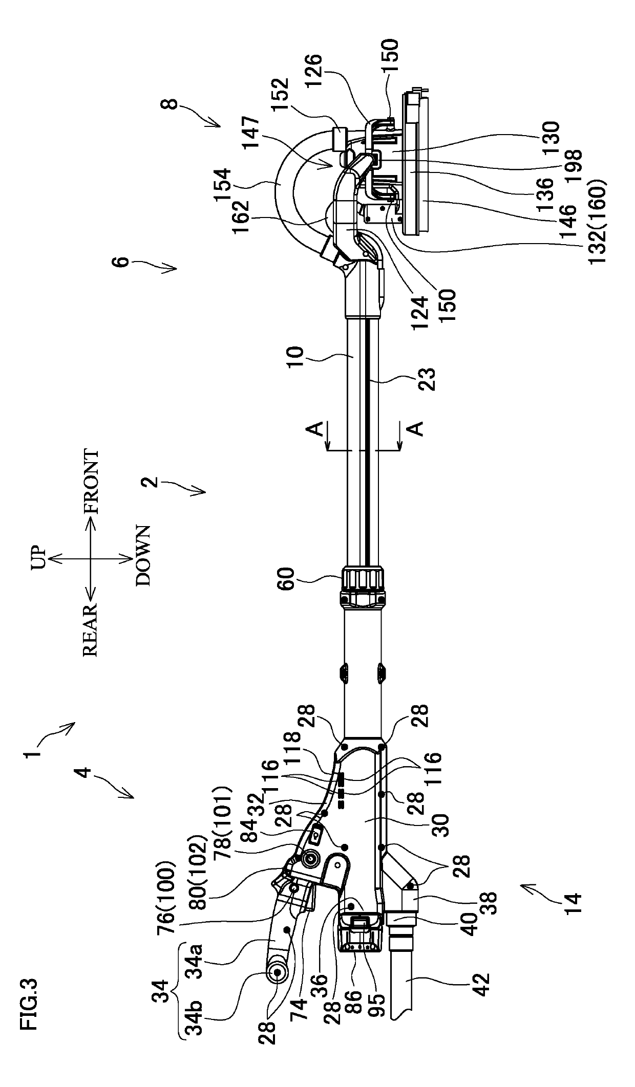
[0053]FIG. 1 is a perspective view when a dry wall sander 1 according to the first embodiment of the disclosure is viewed from a left side. FIG. 2 is a perspective view when the dry wall sander 1 is viewed from a right side. FIG. 3 is a right side view of the dry wall sander 1. FIG. 4 is a front view of the dry wall sander 1. FIG. 5 is a center vertical cross-sectional view of a front of a rear portion of the dry wall sander 1. FIG. 6 is a center vertical cross-sectional view of a rear of the rear portion of the dry wall sander 1. FIG. 7 is a center vertical cross-sectional view of a front portion of the dry wall sander 1. FIG. 8 is a cross-sectional view taken along a line B-B in FIG. 6. FIG. 9 is a cross-sectional view taken along a line A-A in FIG. 3. FIG. 10 is a drawing equivalent to FIG. 1 and illustrates the dry wall sander in a state where the rod portion 2 is at its shortest length.

[0054]The dry wall sander 1 includes a rod portion 2, a handle portion 4, whi...

Example

Second Embodiment

[0165]FIG. 11 is a drawing similar to FIG. 2 where a front portion is omitted in a dry wall sander 251 according to the second embodiment of the disclosure. FIG. 12 is a drawing similar to FIG. 3 where the front portion is omitted in the dry wall sander 251.

[0166]Excluding the number of and a location of battery mounting portions and the number of batteries, the dry wall sander 251 is configured similarly to the dry wall sander 1 according to the first embodiment. Hereinafter, identical reference numerals are given to parts configured similarly to those of the first embodiment and their descriptions are appropriately omitted.

[0167]The dry wall sander 251 includes a handle housing 264 that includes two battery mounting portions 286 in a handle portion 254.

[0168]The one battery mounting portion 286 is located on the right surface of the handle housing 264 and at the rear portion of the rod housing portion 30. The other battery mounting portion 286 is located on the le...

Example

Third Embodiment

[0187]FIG. 13 is a drawing similar to FIG. 2 where a front portion is omitted in a dry wall sander 301 according to the third embodiment of the disclosure. FIG. 14 is a drawing similar toFIG. 3 where the front portion is omitted in the dry wall sander 301.

[0188]Excluding a location of a battery mounting portion, the dry wall sander 301 is configured similarly to the dry wall sander 1 according to the first embodiment. Hereinafter, identical reference numerals are given to parts configured similarly to those of the first embodiment and their descriptions are appropriately omitted.

[0189]A battery mounting portion 336 is formed between the speed adjustment dial 80 and the display unit 118 at a top of a handle housing 314 in a handle portion 304 of the dry wall sander 301.

[0190]The battery 86 is mountable to the battery mounting portion 336. While the longest side J of the battery 86 is in the front-rear direction and the battery button 95 is on the front side, the batte...


PUM


Abstract

A long rod polishing device includes a prismatic or columnar battery, a battery mounting portion, an electric motor, a pad, and a rod portion. The battery is mountable to the battery mounting portion. The electric motor is driven by an electric power from the battery. The pad has a polishing surface and moves by a driving force from the electric motor. The rod portion has an end portion to which the pad is coupled. The battery mounted to the battery mounting portion has a longest side. The longest side has a direction so as to form an angle with respect to a second imaginary straight line. The second imaginary straight line is perpendicular to both of a center axis of the rod portion and a first imaginary straight line. The first imaginary straight line is perpendicular to the center axis and parallel to the polishing surface of the pad.

Description

BACKGROUND[0001]This application claims the benefit of Japanese Patent Application Number 2018-016666 filed on Feb. 1, 2018, the entirety of which is incorporated by reference.TECHNICAL FIELD[0002]This disclosure relates to a long rod polishing device including a dry wall sander, a long rod polisher, a long rod grinder, and a long rod concrete plane.RELATED ART[0003]As illustrated in FIG. 5 in EP Patent Application Publication No. 1961518, there has been known a long rod polishing / cleaning machine using a storage battery 180.[0004]This machine includes a long holding mechanism 12.[0005]As illustrated in FIG. 4, the holding mechanism 12 has one end where bars 78a, 78b are formed in parallel. Between distal end portions of the bars 78a, 78b, a tool head 16 is rotatably coupled via a pair of pin portions 84. The tool head 16 includes a tool 98 like a cleaning tool or a polishing tool.[0006]Meanwhile, a driving motor 178 is located at the other end of the holding mechanism 12 so as to r...

Claims


Application Information

Patent Timeline
IPC IPC(8): B24B23/00B24B27/00
CPCB24B23/005B24B27/0007B24B23/04B24B23/02B24B47/12B24B55/102B24B7/184
Inventor SUGITA, FUMIHIDE
Owner MAKITA CORP
Why Eureka
Try Eureka