Apparatus for Converting Rotation Motion to Linear Reciprocating Motion

a technology of rotating motion and reciprocating motion, applied in the direction of cams, gearing elements, gearing, etc., can solve the problems of reducing affecting the efficiency of anaerobic digestion, and affecting the wear of strategic components of the system

Active Publication Date: 2019-08-01
ENVIRODYNE SYST
View PDF12 Cites 2 Cited by
  • Summary
  • Abstract
  • Description
  • Claims
  • Application Information

AI Technical Summary

Benefits of technology

[0004]The needs remaining in the prior art are addressed by the present invention, which relates to apparatus for generating linear, reciprocating motion and, more particularly, to an apparatus utilizing a cam follower arrangement to convert rotational motion to linear, reciproc

Problems solved by technology

These sliding elements are known to produce friction and results in wear of the strategic components of the system.
Additionally, conventional linear motion systems are imbalanced, where much of the

Method used


Image

  • Apparatus for Converting Rotation Motion to Linear Reciprocating Motion
  • Apparatus for Converting Rotation Motion to Linear Reciprocating Motion
  • Apparatus for Converting Rotation Motion to Linear Reciprocating Motion

Examples


Embodiment Construction

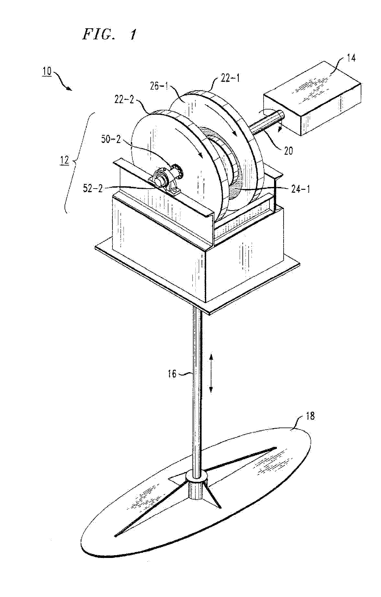
[0019]FIG. 1 is a simplified view of an exemplary linear motion mixer 10 including a motion conversion apparatus formed in accordance with the present invention. As will be described in greater detail below, mixer 10 includes a conversion unit 12 for converting circular motion into a linear, reciprocating motion. A power unit 14 is attached to conversion unit 12 and is used to impart circular, rotational motion to, conversion unit 12. A linear motion shaft 16 is also attached to conversion unit 12 and, in response to, the rotational movement of conversion unit 12, moves upward and downward in a reciprocating manner, as shown by the double-ended arrow in FIG. 1. A mixing paddle 18 (of any desired configuration) is attached to a distal end of shaft 16 and is used to impart mixing to the material (not shown) in a known manner. In the embodiment illustrated in FIG. 1, mixing paddle 18 is shown to exhibit an elliptical form. Many other paddle configurations are possible including, but no...


PUM


Abstract

A pair of spaced-apart cam disks disposed along a common power shaft, with a pair of cam followers disposed within channels formed in opposing inner surfaces of the cam disks, forms a balanced arrangement for creating linear reciprocating motion from the rotation of the pair of cam disks. A linear motion shaft is coupled to the cam followers. As the cam disks synchronously rotate and the cam followers trace the path formed by the paired channels, this rotational motion is converted into linear, reciprocal motion that provides the translational movement of the linear motion shaft.

Description

TECHNICAL FIELD[0001]The present invention relates to apparatus for generating linear, reciprocating motion and, more particularly, to an apparatus utilizing a cam follower arrangement to convert rotational motion to linear, reciprocating motion without requiring the use of sliding parts.BACKGROUND OF THE INVENTION[0002]Many of the industrial mixing systems in use today are based on linear motion technology, providing a linear, vertical motion of a mixing shaft within a reactor. As designed, current systems depend on sliding, elements in the motion conversion system. These sliding elements are known to produce friction and results in wear of the strategic components of the system. Additionally, conventional linear motion systems are imbalanced, where much of the energy expended in retracting the linear motion shaft results from the lifting the yoke assembly.[0003]One particular use for linear motion mixing is associated with the treatment of waste products in anaerobic digester tank...

Claims


Application Information

Patent Timeline
IPC IPC(8): F16H25/14F16H53/02
CPCF16H25/14F16H53/02F16H53/06
Inventor SHEKER, ROBERT E.SHANAFELTER, ROYBUSHEY, ERIC ALAN
Owner ENVIRODYNE SYST
Why Eureka
Try Eureka