
System and method for reduced overhead feedback scheme for interference mitigation in cellular networks

a technology of overhead feedback and interference mitigation, applied in the field of cellular networks, can solve the problems of limiting the overall network throughput, limiting the range of interference, and being less suitable for moderate/high doppler spread, so as to reduce interference channel dimensions, reduce congestion, and improve interference suppression

Active Publication Date: 2019-08-01
BAR ILAN UNIV
View PDF6 Cites 0 Cited by
  • Summary
  • Abstract
  • Description
  • Claims
  • Application Information

AI Technical Summary

Benefits of technology

This patent is about a system and method for reducing interference and improving signal quality in a wireless network. The method involves restricting the interfering base station to a specific signal space, which reduces the dimensions of the interference channel. The system also includes a mechanism for reducing residual interference to non-intended user equipment devices. This iterative process helps to maintain a high signal-to-noise ratio in the network. Overall, the system and method described in this patent help to improve the quality of wireless signals and facilitate better communication.

Problems solved by technology

Increasing capacity is a very challenging task due to the scarcity of the available electromagnetic spectrum and the aggressive frequency reuse; i.e., the same frequencies are used concurrently by adjacent Base Stations (BSs).
This creates interference between BSs and User Equipment devices (UEs) in adjacent cells, interference which is a major factor in limiting overall network throughput.
In general, iterative schemes provide good performance in slow varying channels, but are less suitable for moderate / high Doppler spread.
Despite the progress in reducing CSI feedback overhead, or compensating for limited feedback, this constraint is still a major factor in limiting CoMP performance, and is recognized as an important challenge in the development of 5G networks.

Method used


Image

  • System and method for reduced overhead feedback scheme for interference mitigation in cellular networks
  • System and method for reduced overhead feedback scheme for interference mitigation in cellular networks
  • System and method for reduced overhead feedback scheme for interference mitigation in cellular networks

Examples


Embodiment Construction

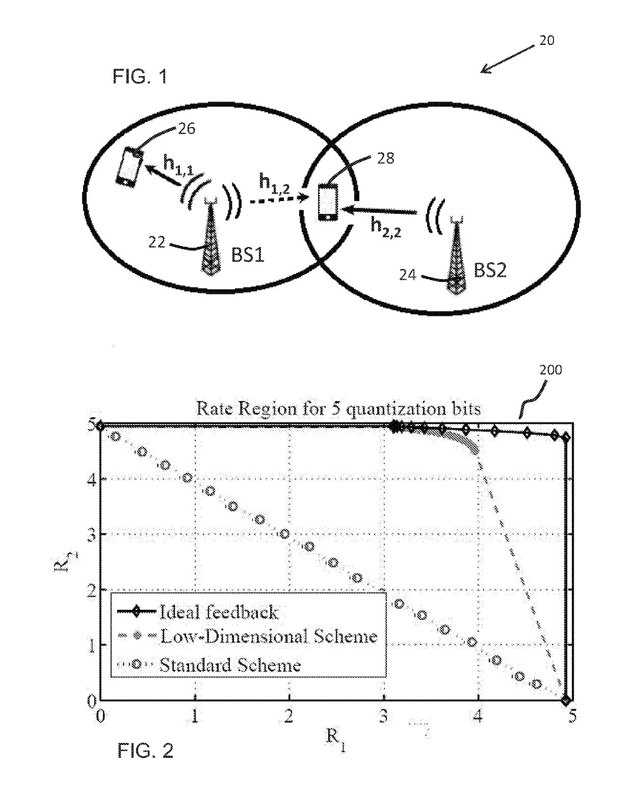
[0019]Reference is now made to FIG. 1, showing a simplified diagram of a cellular network 20 comprising two cellular base stations BS1 (22) and BS2 (24) and two cellular user equipment devices UE1 (26) and UE2 (28). It is to be understood that more base stations and user equipment devices are typically active in a, cellular network.

[0020]UE1 is being serviced by BS1. UE2 is being serviced by BS2 while also receiving signals from BS1; that is, the signals of BS1 sensed by UE2 interfere with the signals received from BS2. The network may be analyzed as a multiple-input, single-output (MISO) interference channel, where each BS employs n transmit antennas, and each UE employs a single receiver antenna.

[0021]BS transmitters transmit initial signals, which may be pilot or training signals, from which the served UEs (intended UEs) estimate the direct channels. Let ĥu, i=1, 2, denote the estimated direct channel in a first round of channel estimation.

[0022]Network 20 is a two-user MISO inte...


PUM


Abstract

A system and methods are provided for reducing radio interference in a cellular network comprising a plurality of Base Stations (BSs) and a plurality of User Equipment devices (UEs). The method includes receiving at a base station (BS) serving a user equipment device (UE) a feedback signal, estimated by the UE in response to a radio signal, wherein the feedback signal includes a quantized representation of a direct channel of the BS. The method further includes determining at the BS a pre-coding matrix having a smaller number of dimensions than a number of antennas of the BS and applying the pre-coding matrix to filter subsequent radio signals transmitted by the BS.

Description

FIELD OF THE INVENTION[0001]The present, invention relates to cellular networks in general, and in particular to systems and methods for reducing interference in cellular networks.BACKGROUND OF THE INVENTION[0002]Mobile communication has developed extensively in the past few decades in terms of the diversity of applications, data rates, and the heterogeneity of device types. This growth requires constant technological advances to meet the increasing quality of service and capacity demand. Increasing capacity is a very challenging task due to the scarcity of the available electromagnetic spectrum and the aggressive frequency reuse; i.e., the same frequencies are used concurrently by adjacent Base Stations (BSs). This creates interference between BSs and User Equipment devices (UEs) in adjacent cells, interference which is a major factor in limiting overall network throughput. Thus, different levels of coordination / cooperation among BSs, known as Coordinated Multi-point (CoMP) techniq...

Claims


Application Information

Patent Timeline
Patent Type & Authority Applications(United States)
IPC IPC(8): H04B7/0456H04L5/00H04B7/06H04B7/0452
CPCH04B7/0482H04L5/0035H04B7/0626H04B7/0452H04B7/0456
Inventor NOAM, YAIRZAIDEL, BENJAMIN MOSHEKLMELFELD SHAHAK, NAAMA
Owner BAR ILAN UNIV
Learn More