
Audio Source Waveguide

a waveguide and audio technology, applied in the field of audio source waveguides, can solve the problems of negative affecting the overall sound that reaches the listener, and achieve the effect of improving the flow of air and improving the quality of sound

Active Publication Date: 2019-08-01
QUEST ENGINES LLC
View PDF0 Cites 3 Cited by
  • Summary
  • Abstract
  • Description
  • Claims
  • Application Information

AI Technical Summary

Benefits of technology

The present invention aims to improve the quality of sound produced by an audio source and enhance the flow of air through a port provided in the audio source enclosure. Additionally, it allows the port to be positioned in a location that provides acoustic and aesthetic advantages over known port locations.

Problems solved by technology

The pressure waves generated by the backside of the speaker propagate within the enclosure, and depending upon the enclosure design, may negatively affect the overall sound that reaches the listener.

Method used


Image

  • Audio Source Waveguide
  • Audio Source Waveguide
  • Audio Source Waveguide

Examples


Embodiment Construction

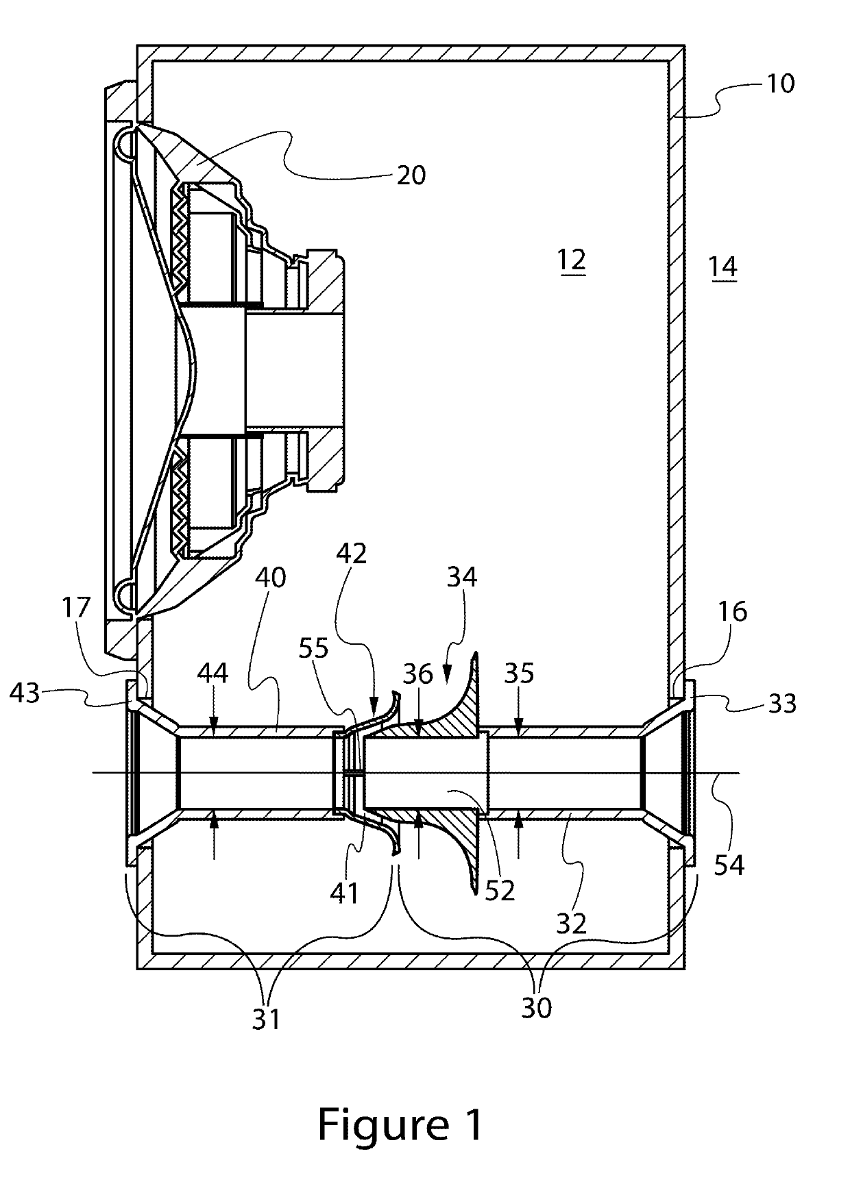
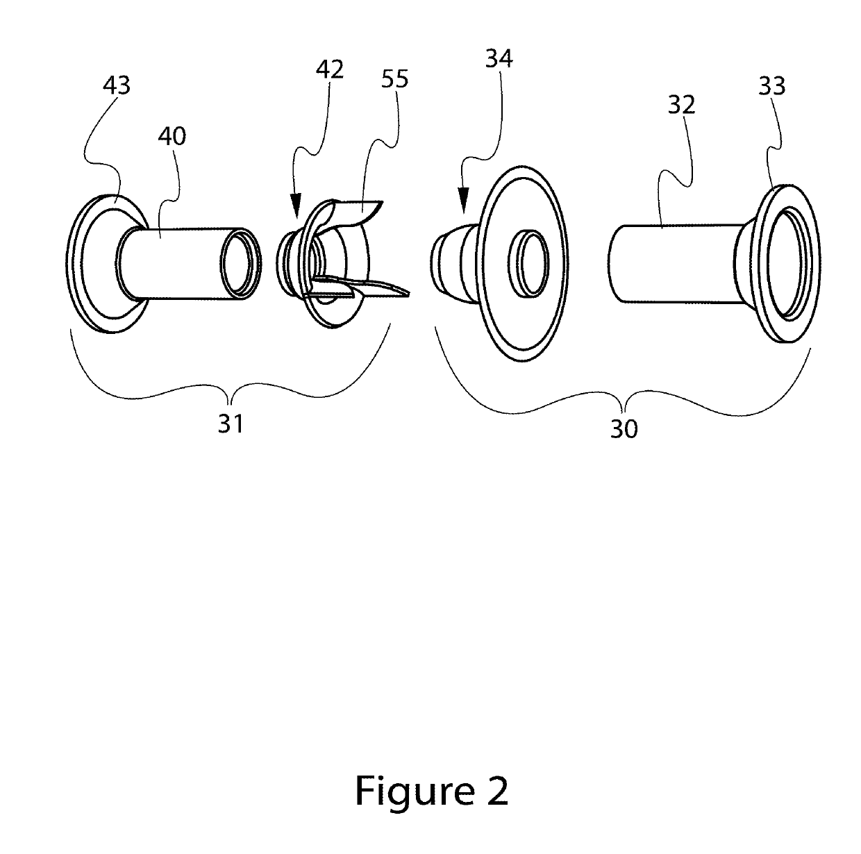
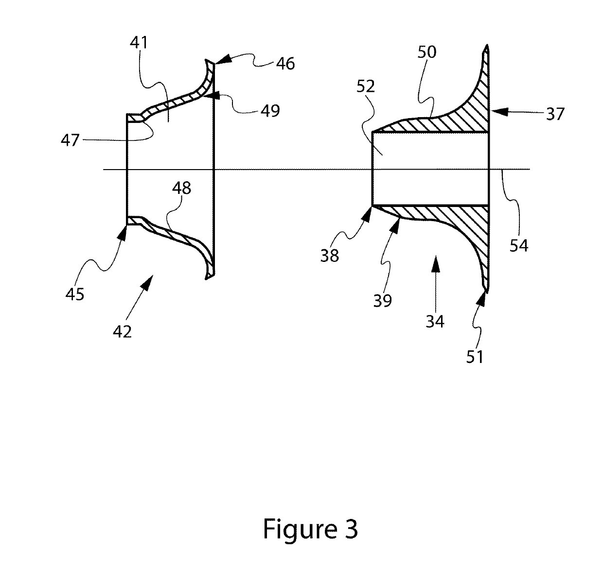
[0019]Responsive to the foregoing challenges, Applicant has developed an innovative audio source comprising: an enclosure generally defining an enclosure interior and an enclosure exterior, said enclosure having a first opening extending between the enclosure interior and enclosure exterior; a first waveguide section including a first passage in fluid communication with a first hollow portion of a first funnel, said first funnel including a first surface generally flaring away from the first passage between a first funnel end and a first funnel tip; and a second waveguide section including a second passage in fluid communication with a second hollow portion of a second funnel, said second funnel including a second surface generally flaring away from the second passage between a junction of the second passage with the second funnel and a second funnel end, wherein one or both of the first waveguide section and the second waveguide section extend from the first opening, wherein the fi...


PUM


Abstract

Embodiments of apparatus for affecting air flow and / or pressure wave propagation in relation to an audio source enclosure are disclosed. The apparatus may include two waveguide sections mounted within an audio source enclosure. The waveguide sections may include complementary nested first and second funnels disposed relative to each other in a manner to channel air flow in and / or from the enclosure.

Description

CROSS REFERENCE TO RELATED APPLICATIONS[0001]This application relates to and claims the priority of U.S. Provisional Patent Application No. 62 / 622,645, which was filed Jan. 26, 2018.FIELD OF THE INVENTION[0002]Embodiments of the present invention relate generally to apparatus for affecting air flow and / or pressure wave propagation in relation to an audio source enclosure.BACKGROUND OF THE INVENTION[0003]Many devices, systems and processes utilize the flow of a working fluid, such as air for example, between two locations relative to a structure. Flow of a working fluid may occur in concert with the propagation of pressure waves in the working fluid. The desired flow of the working fluid and / or propagation of pressure waves can be inhibited by the interaction of the structure with the working fluid. For example, frictional forces between the structure and the working fluid may impart a drag force on the working fluid. The efficient and controlled operation of devices, systems and pro...

Claims


Application Information

Patent Timeline
Patent Type & Authority Applications(United States)
IPC IPC(8): H04R1/28H04R1/02H04R19/02
CPCH04R1/2826H04R1/2803H04R1/026H04R19/02H04R2201/029H04R2499/13H04R1/2888H04R1/2896F02B17/005F02M61/08F02M61/166F02M61/18
Inventor DALMAS, II, ELARIO D.LEATHERS, BRETT J.
Owner QUEST ENGINES LLC
Learn More