Layered structure with embedded graphical pattern

a multi-layered structure and embedded technology, applied in the field of optically transmissive multi-layered structure, can solve the problems of affecting the transparency of the underlying surface, unable to provide the means for adding decorative or informative visual elements directly onto the display screen, and difficult to utilize the surface for other purposes, for instance advertising or decorative purposes, to achieve the effect of extending utility, simple, and extending utility

Active Publication Date: 2019-08-08
DOCOVER OY
View PDF0 Cites 4 Cited by
  • Summary
  • Abstract
  • Description
  • Claims
  • Application Information

AI Technical Summary

Benefits of technology

The patent describes a method for creating a protective layer for electronic devices that reflects light with higher incidence angles and transmits light with lower incidence angles. This makes the device more visible in the presence of light with higher angles and less visible in the presence of light with lower angles. The protective layer also acts as a barrier to external impact, preventing damage to the device. The method is cost-effective, flexible, and can be easily attached to any shape or bended without breaking the structure.

Problems solved by technology

The apparent need for sufficient transparency to be maintained in many circumstances, such as in displays for electronic devices or in windows e.g. for doors, vehicles, building structures, lighting devices, and various signs, makes it difficult to utilize the surface for other purposes, for instance advertising or decorative purposes.
Such objects will, however, severely interfere with transparency of the underlying surface, which will be a considerable disadvantage in cases where a certain level of transparency is nevertheless required at least intermittently for appropriate use of the surface material.
These methods in turn do not provide means for adding decorative or informative visual elements directly onto the display screen that do not severely obstruct the user's view of the display when the device and display are in use.

Method used


Image

  • Layered structure with embedded graphical pattern
  • Layered structure with embedded graphical pattern

Examples


Embodiment Construction

[0027]The term “light” herein refers to, but is not limited to wavelengths in the visible range of the electromagnetic spectrum.

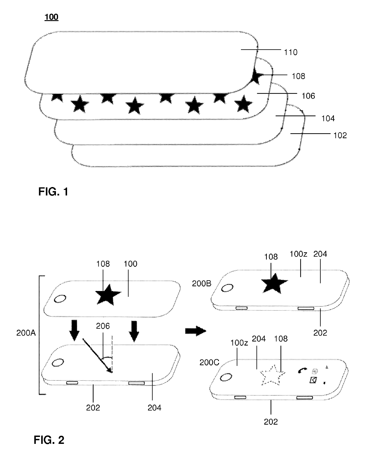
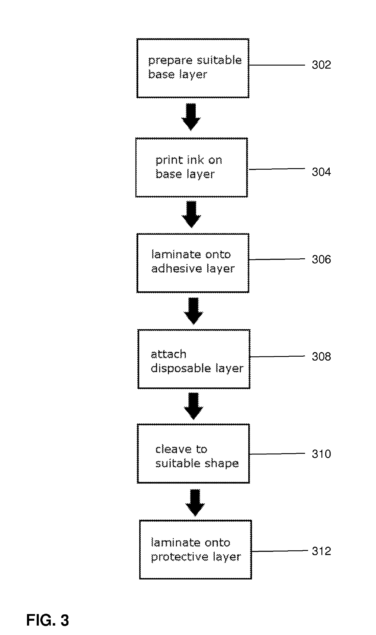
[0028]According to one embodiment of the present invention, a layered structure 100 depicted in FIG. 1 may be manufactured through integration incorporating lamination, for instance.

[0029]The embodiment comprises a disposable layer 102, an adhesive layer 104, a base layer 106, ink pattern 108, and a protective layer 110. In some embodiments, one or all of the layers 102, 104, or 110 may be excluded from the embodiment.

[0030]The disposable layer 102 may be composed of a material of choice which is convenient for the embodiment. For the embodiment of FIG. 1, for example paper or a plastic such as polyvinyl chloride or polyethylene may be used. The disposable layer 102 may basically protect the adhesive layer 104 during storage and transportation, for example.

[0031]The adhesive layer 104 may comprise any transparent adhesive, such as a multi-component adhesive...


PUM

PropertyMeasurementUnit
Percent by massaaaaaaaaaa

Abstract

A method is presented for producing an optically transmissive layered structure for use as a display protector for electronic devices. The method comprises printing an ink pattern on a base layer, where said base layer is substantially optically transparent, and the base layer and ink are configured so that the ink reflects light with high incidence angle and transmits light with low incidence angle, when in use, thus displaying the pattern in the absence of light with high intensity and low incidence angle, the pattern becoming substantially undetectable otherwise.

Description

FIELD OF THE INVENTION[0001]The invention relates to an optically transmissive multilayered structure that can be placed on the surface of a target entity, said structure incorporating a visual design. More specifically, however not exclusively, the invention relates to such a structure for use as a display protector for electronic devices comprising a printed pattern that is, depending on the lighting conditions, for instance, more clearly visible or remain substantially undetected by a viewer.BACKGROUND OF THE INVENTION[0002]Transparent materials such as glass or acrylic are generally widely used in various applications. The apparent need for sufficient transparency to be maintained in many circumstances, such as in displays for electronic devices or in windows e.g. for doors, vehicles, building structures, lighting devices, and various signs, makes it difficult to utilize the surface for other purposes, for instance advertising or decorative purposes. Yet, there may also be a des...

Claims


Application Information

Patent Timeline
IPC IPC(8): B44F1/06B32B7/12B32B7/06B32B27/08B32B27/30B32B17/06B32B27/36B44F1/10C09D11/037C09D11/06C09D11/322C09D11/36G02B1/14H04M1/02H04B1/3888
CPCB44F1/066B32B7/12B32B7/06B32B27/08B32B27/308B32B27/306B32B17/064B32B27/36B32B27/365B44F1/10C09D11/037C09D11/06C09D11/322C09D11/36G02B1/14H04M1/0283H04B1/3888B32B2255/10B32B2255/205B32B2264/105B32B2307/412B32B2307/414B32B2307/584B32B2307/732B32B2451/00B41M3/00B41J2/485B32B17/06B32B17/10B41M3/148G02B5/26G02B5/3066G02F1/1323G02F1/133509G02F1/133516Y10T428/1462
Inventor HYVONEN, TEPPORONKAINEN, JARITOIMELA, ATSOPENG, PUSHENG
Owner DOCOVER OY
Why Eureka
Try Eureka