Tourniquet

a technology of tourniquets and clamping rods, which is applied in the field of tourniquets, can solve the problems of lack of robustness, lack of controllable adjustment of the tensioning rod, and often wholly mechanical nature of the tourniquet, and achieves the effects of less pull force, less pull force, and convenient single-handed operation

Active Publication Date: 2019-08-15
ARISTEIA AS
View PDF0 Cites 7 Cited by
  • Summary
  • Abstract
  • Description
  • Claims
  • Application Information

AI Technical Summary

Benefits of technology

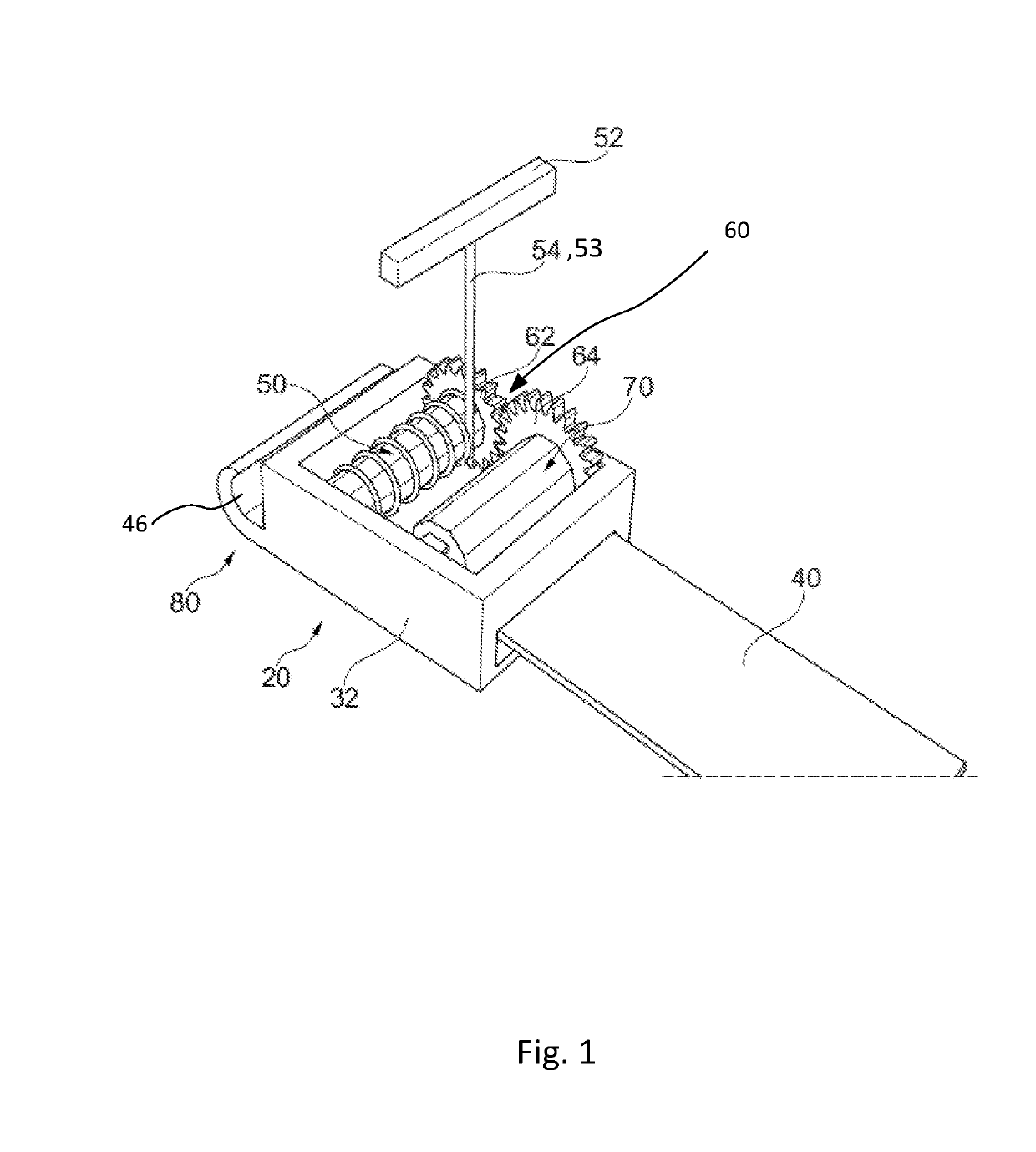
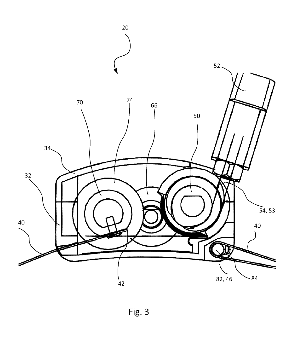
[0059]In the disclosed tourniquets according to the present invention, the translation ratio from the reel to the arbor via the gear system is chosen such that one rotation of the reel results in one or more rotations of the arbor, preferably a ratio of 1:3. This is preferred in cases, where it would be advantageous to provide more rapid tightening of the tourniquet. In particular preferred embodiments of the tourniquet the translation ratio is chosen such that one rotation of the reel results in less than one rotation of the arbor, preferably a ratio of 2:1 or 3:1. The advantage of this ratio is that less pull force is needed for tightening of the tourniquet.
[0060]The length of the pull-cord in the disclosed tourniquets according to the present invention is typically chosen in such a way that it can easily be operated single handed e.g. if the user is the injured person himself / herself. The pull-cord can typically have a length of 20 cm to 60 cm to be pulled using only one arm. The pull-cord may be shorter than 20 cm to allow a smaller dimension of the pull-cord reel. The pull-cord may be longer than 60 cm to allow an operator to apply more force to the arbor in a single movement. The pull cord handle may be configured for operation by one hand and / or two hands. In circumstances where there is not sufficient space for the full length of the pull cord to be pulled, this can be compensated by pulling the pull cord multiple times to attain the same constriction as pulling the full length of the pull cord.

Problems solved by technology

Contrary to surgical tourniquets which utilize pneumatic systems to attain the necessary occlusion pressure, tactical tourniquets are often wholly mechanical in nature due to concerns of durability and reliability.
There are several disadvantages of many of the known tourniquets such as lack of robustness, lack of possibilities for controlled adjustments of the constriction, afforded power in the constriction, time used for the constriction as well as effectiveness and ease in handling the tourniquet by non-medical and medical persons potentially exposed to extreme situations.
A disadvantage of this tourniquet is the time taken to achieve occlusion due to a slow adjustment mechanism.
One disadvantage of this tourniquet is a problematic use with one arm.
A disadvantage of this tourniquet is a cumbersome operation.
A disadvantage of this tourniquet is a problematic use with one arm.
Also this tourniquet is problematic to use with one arm only.

Method used


Image

  • Tourniquet
  • Tourniquet
  • Tourniquet

Examples


second embodiment

[0112]During assembly of the tensioning mechanism, the arbor 70, the gear system 62, 64, 66, and the recoil reel 50 are held in place by the brackets 100,102 when fitted inside the base 32 and when the cover 34 is attached. The brackets 100, 102 are held in place by fitted slots in the base 32. The handle 52 of the recoil reel 50 will then be located externally to the housing. A schematically view of the mechanical workings of the second embodiment is shown in FIG. 5.

[0113]In FIG. 6 is shown a view of the housing of the second embodiment where the cover 34 has been removed. The brackets 102, 100 fix the arbor 70 and the recoil reel 50 inside the base 32. The strap 40 is entered through an opening in the base 32 and fixed to the arbor 70. Linear force applied by pulling the handle 52 is transferred to the arbor 70 via the gear wheel system and the strap 40 is winded up on the arbor 70.

[0114]In FIG. 7 is shown an exploded view of a third exemplary embodiment of a tourniquet according ...

third embodiment

[0116]FIG. 8 shows a cross sectional view of the tension device of the tourniquet 10. The housing 32 is surrounding the inner mechanics of the tensioning device. The spring 79 is placed inside the inner cylinder 75. The balls 77 are resting against the cone shaped section 132 of the pins 120 inside the inner cylinder 75. The inner cylinder 75 is inside the arbor 70. There is at least one longitudinal groove 71 inside the arbor 70 extending into the area where the balls contact the arbor 70 through the recesses in the inner cylinder 75. When the spring loaded ball locking mechanism is enabled, the balls 77 are pushed against a corresponding groove 71 and are locking the inner cylinder to the arbor 70. The balls 77 are pushed through a corresponding recess in the inner cylinder 75 as described above. When the spring loaded ball lock mechanism is enabled, the inner cylinder and the arbor are rotatable locked to each other. Pushing the pins 120 in the longitudinal direction of the inner...


PUM


Abstract

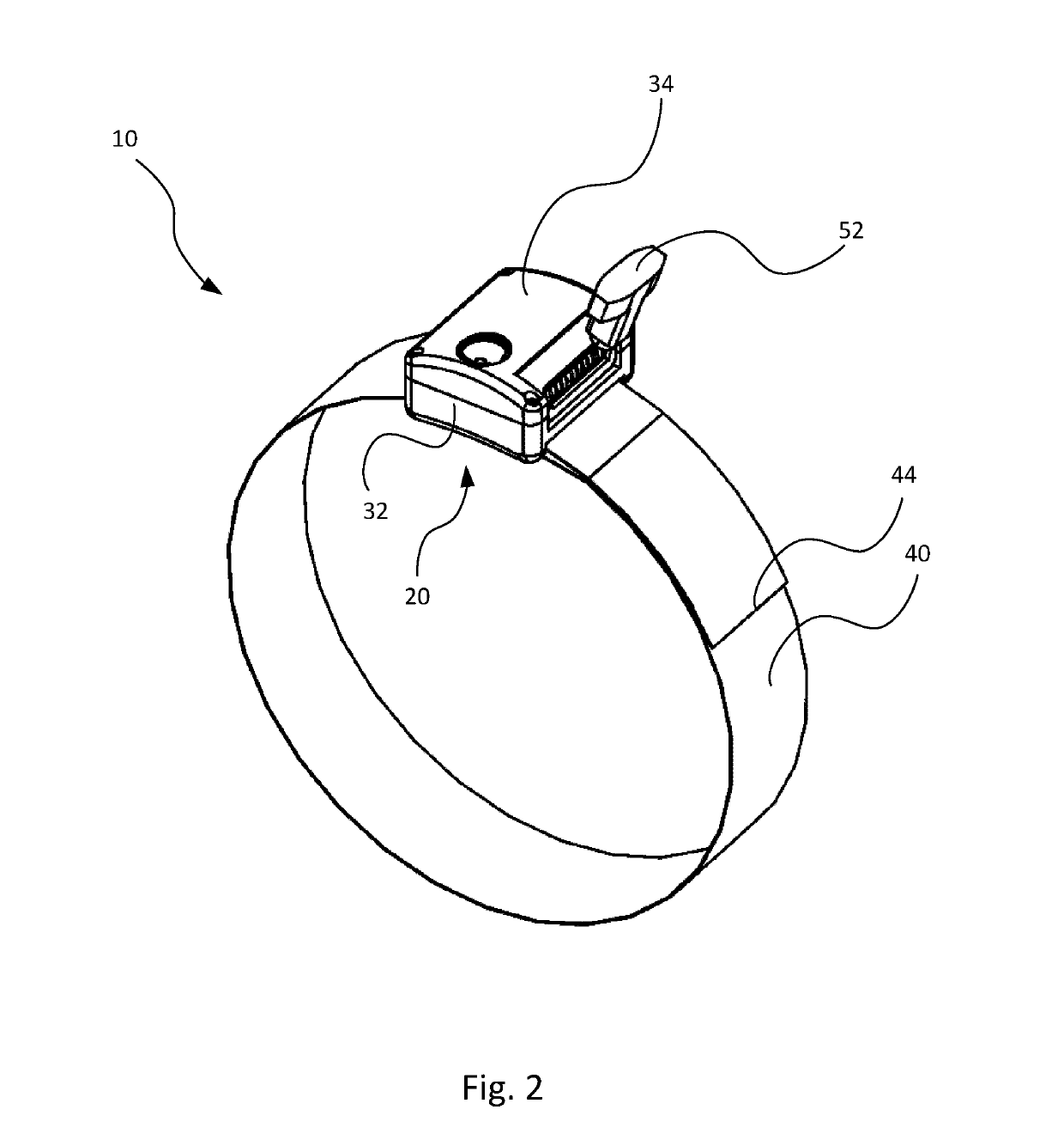
The present invention relates a tourniquet, where tightening of the tourniquet is performed by linear motion by pulling a pull-cord. The tourniquet comprises a tensioning device and a strap. The first end of the strap is coupled to the tensioning device. The second end of the strap is wrapped around a limb and fixed to the tensioning device. The tightening of the tourniquet is achieved by pulling a pull-cord. Linear motion by the pull-cord is translated into winding up the strap inside the tensioning device, and thereby achieving a time-effective tightening of the tourniquet without the need of high forces.

Description

TECHNICAL FIELD OF THE INVENTION[0001]The present invention relates to a tourniquet comprising a strap having a first and a second end for encircling a limb; and a tensioning device comprising a housing wherein the housing comprises at least a first arbor for attaching and winding the first end of the strap; a fastening means for affixing the second end of the strap to the housing; a rotation generating means for providing rotations for the winding in of the strap; a coupling for transferring of rotations from the rotation generating means to the arbor and a locking mechanism to prevent unwinding of the strap.[0002]Said tourniquet is useful for medical and therapeutic treatment of an injured individual.BACKGROUND OF THE INVENTION[0003]Tourniquets function by constricting the extremity in such a way that the blood flow is occluded. This provides a way for medical personnel and first responders to stabilize the patient in a pre-hospital setting, often at the site of injury. The tourni...

Claims


Application Information

Patent Timeline
Patent Type & Authority Applications(United States)
IPC IPC(8): A61B17/132
CPCA61B17/1327A61B17/1325A61B2017/00477A61B2017/00876A61B2090/0807A61B17/132A61B17/1322
Inventor FOSTAD MOE, GARD
Owner ARISTEIA AS
Why Eureka
Try Eureka