Method for electronically controlling a brake unit in an automatically controllable utility vehicle combination, and electronically controllable brake unit in an automatically controllable utility vehicle combination

a technology of electronically controlling and brake unit, which is applied in the direction of braking system, braking components, transportation and packaging, etc., can solve the problems of increasing assembly and cost expenditure, and the ability to retrofit is only possible with increasing expenditur

Active Publication Date: 2019-08-15
ZF CV SYST EURO BV
View PDF0 Cites 9 Cited by
  • Summary
  • Abstract
  • Description
  • Claims
  • Application Information

AI Technical Summary

Benefits of technology

[0011]In an embodiment, the present invention provides a method for electronically controlling a brake unit having two brake systems in an automatically controllable vehicle combination. The method includes inputting a request signal for automatic electronic activation of service brakes in a tractor vehicle brake system of a tractor vehicle and/or a trailer brake system of a trailer of the vehicle combination, wherein an automatically requested vehicle setpoint acceleration and/or an automatically requested vehicle setpoint velocity to be implemented by the respective service brakes are transmitted via the request s...

Problems solved by technology

To form an automatically activatable redundancy in such brake units, in particular in automatically controlled utility vehicles and utility vehicle combinations, which can intervene automatically in the event of a defect in the electronic activation of the axle modulators and if no driver is in the vehicle or at the d...

Method used


Image

  • Method for electronically controlling a brake unit in an automatically controllable utility vehicle combination, and electronically controllable brake unit in an automatically controllable utility vehicle combination
  • Method for electronically controlling a brake unit in an automatically controllable utility vehicle combination, and electronically controllable brake unit in an automatically controllable utility vehicle combination
  • Method for electronically controlling a brake unit in an automatically controllable utility vehicle combination, and electronically controllable brake unit in an automatically controllable utility vehicle combination

Examples


Embodiment Construction

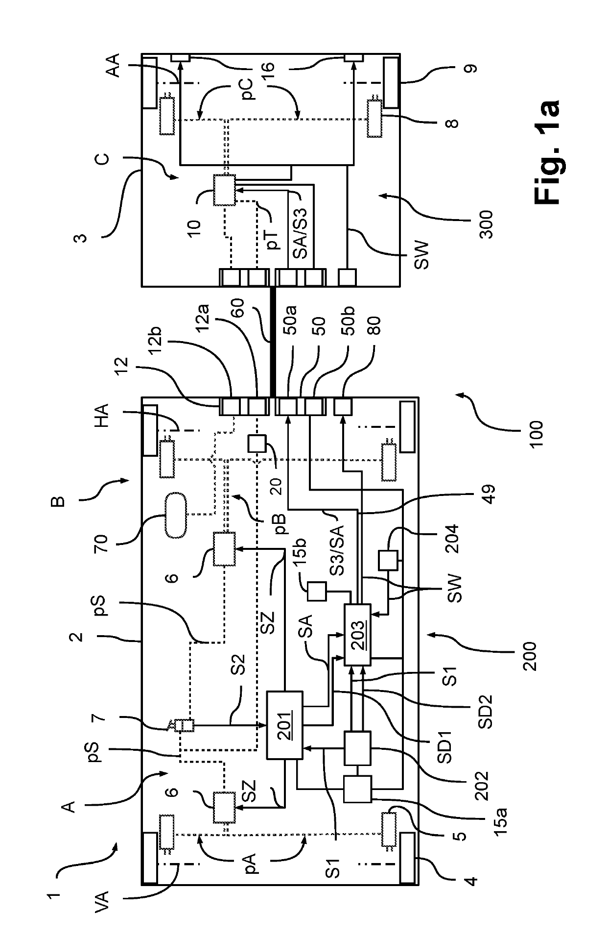
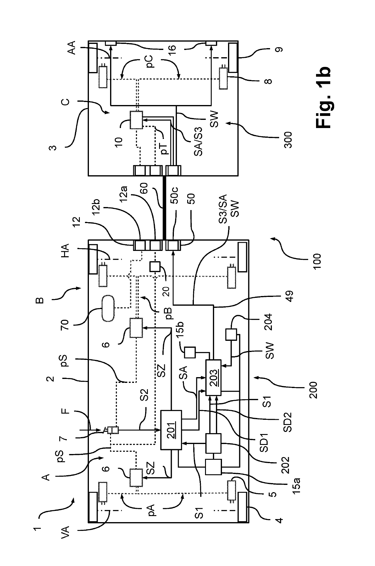
[0016]Embodiments of the invention provide methods for electronically controlling a brake unit in an automatically controllable utility vehicle combination, by which a secure and reliable electronically controlled braking can be ensured with little effort in case of fault. Furthermore, embodiments of the invention provide electrically controllable brake units for automatically controllable utility vehicle combinations.

[0017]It is therefore recognized according to the invention that in a vehicle combination, in particular in an automatically controllable utility vehicle combination, in the event of a failure in the electrical activation of service brakes of the vehicle combination—i.e., in case of fault—it is solely important that the vehicle can be transferred safely into a decelerated state. The safely decelerated state can mean in this case, depending on the fault and application, immediate deceleration to a standstill, stopping on the shoulder or in an emergency stop bay, or taki...


PUM


Abstract

A method for electronically controlling a brake unit having two brake systems in an automatically controllable vehicle combination includes inputting a request signal for automatic electronic activation of service brakes in a tractor vehicle brake system of a tractor vehicle and/or a trailer brake system of a trailer of the vehicle combination, wherein an automatically requested vehicle setpoint acceleration and/or an automatically requested vehicle setpoint velocity to be implemented by the respective service brakes are transmitted via the request signal. The method further includes monitoring and checking plausibility of the request signal to establish whether the automatically requested vehicle setpoint acceleration and/or the automatically requested vehicle setpoint velocity are or can be implemented completely or faultlessly by the respective service brakes. The method additionally includes outputting a trailer redundancy control signal at the trailer brake system under certain conditions.

Description

CROSS REFERENCE TO RELATED APPLICATIONS[0001]This application is a U.S. National Stage Application under 35 U.S.C. § 371 of International Application No. PCT / EP2017 / 000862 filed on Jul. 17, 2017, and claims benefit to German Patent Application No. DE 10 2016 010 461.9 filed on Aug. 31, 2016. The International Application was published in German on Mar. 8, 2018 as WO 2018 / 041387 A1 under PCT Article 21(2).FIELD[0002]The invention relates to a method for electronically controlling a brake unit, in particular a pneumatic brake unit, in an automatically controllable utility vehicle combination, and an electronically controllable brake unit, in particular a pneumatic brake unit, in an automatically controllable utility vehicle combination.BACKGROUND[0003]In vehicle combinations, in particular utility vehicle combinations, consisting of a tractor vehicle and a trailer, in which an electronically controllable pneumatic tractor vehicle brake system is used in the tractor vehicle and an elec...

Claims


Application Information

Patent Timeline
IPC IPC(8): B60T8/17B60T17/22B60T8/1761B60T13/62B60Q1/44B60T7/04B60T7/20B60T8/32B60T8/88B60T13/26B60T13/68
CPCB60T8/1708B60T17/221B60T8/17616B60T13/62B60Q1/44B60T7/042B60T7/20B60T8/323B60T8/885B60T13/263B60T13/683B60T2270/402B60T2270/82B60T2270/10B60T2270/404B60T2270/414
Inventor WULF, OLIVER
Owner ZF CV SYST EURO BV
Why Eureka
Try Eureka