Combination Of A Plug And A Cover

a plug and cover technology, applied in the direction of electrical apparatus, electrical apparatus casings/cabinets/drawers, etc., can solve the problems of increased space requirements of screw arrangement of this kind, inability to use additional fastening parts, and inability to mechanically clamp the plug and the sheet metal cover

Active Publication Date: 2019-08-15
VITESCO TECH GERMANY GMBH
View PDF7 Cites 1 Cited by
  • Summary
  • Abstract
  • Description
  • Claims
  • Application Information

AI Technical Summary

Benefits of technology

[0014]This allows the formation of an interlocking and / or force-fitting mechanical fixing arrangement which acts between the insertion element and the insertion receptacle and which mechanically fixedly connects the plug housing and the cover to one another. In particular, preferably in conjunction with an interlocking holding connection, the cover and the plug housing can be mechanically fixed to one another by a type of stitching process. Projections in the form of hooks, in particular barbs, can preferably be formed laterally on the engagement element and hook-like recesses can preferably be formed on the wall regions, so that projections and recesses interact in an interlocking manner in the assembled state and as a result prevent separation of the cover and the plug housing from one another. With preference, sealing material, in particular curable sealing material, is arranged between the cover longitudinal edge and the plug longitudinal edge and, before complete curing of the sealing material, the cover is preferably mechanically fastened to the plug housing by means of the insertion elements and the insertion receptacles. Therefore, the mechanical fixing can take effect as early as during curing. Said mechanical fixing can advantageously be produced without separate connecting elements, such as screws or clips for example. An insertion element according to the invention can also be called a stitch pin. The mechanical fixing can advantageously already be produced during the course of pressing the cover against the plug housing, this pressing operation taking place in any case owing to the sealing material. Therefore, an additional process is not required for producing the mechanical fixing. A beading process which is known from the prior art in this region could very severely deform the blade strip if, as is frequently the case, the plug is highly elastic in the center. In the case of a combination according to the invention, the introduction of force for the mechanical fixing (the process could also be called a stitching process) can preferably be performed perpendicularly in relation to the sealing geometry, so that it subjects the plug housing only to slight loading. Mechanical fixing of the plug to the cover in this region is possible in all directions by means of insertion elements and insertion receptacles. In the case of a so-called “in-circuit test” which takes place during manufacture, the plug is subjected to severe loading by the pin contact-making operation and deformed. In the case of a combination according to the invention comprising a plug and a cover, sagging of the plug can be minimized by means of the mechanical fixing.
[0028]In order to achieve an elastic snap-action connection which acts in an interlocking manner, it is preferred for the insertion element to be adapted such that it is elastically deformed when it is inserted into the receiving opening when, based on a non-assembled starting state of the plug and the cover, two holding projections of a pair, in the case of which a width of the insertion element is greater than a clear opening width of the receiving opening which is associated with a pair of recesses, are moved through the cross section of the receiving opening with this clear width, so that a reduction in this width results.
[0030]As an alternative or in combination, it is possible for a wall region or the two wall regions of the insertion receptacle to be adapted such that it is or they are elastically deformed and / or shifted when the insertion element is inserted into the receiving opening when, based on a non-assembled starting state of the plug and the cover, two holding projections of a pair, in the case of which a width of the insertion element is greater than a clear opening width of the receiving opening which is associated with a pair of recesses, are moved through the cross section of the receiving opening with this clear width, so that an increase in this clear opening width results.
[0033]It is regarded to be an expedient development, in a cross-sectional plane which is parallel in relation to the element plug-in direction, for two recesses which are formed next to one another to each have an outer contour which corresponds to the outer contour of two holding projections, which are arranged next to one another, in a cross-sectional plane which is parallel in relation to the receptacle plug-in direction. It is regarded as being advantageous, in the case of an orientation of the cover relative to the plug which is suitable, in particular intended, for fitting the cover to the plug, for the insertion element to be in alignment with the receiving opening.
[0035]As a result, the maximum distance between adjacent plug-in connections as viewed in the respective longitudinal direction can be limited and the stability of the combination can be improved in this way. A preferred refinement is regarded as being one in which, in the case of insertion elements and insertion receptacles which are associated with them for fitting purposes and which are arranged comparatively further outward in the plug longitudinal direction and, respectively, in the cover longitudinal direction, the holding projections and recesses are matched to one another such that, in the assembled state, a comparatively smaller overlap between supporting faces and holding faces results than in the case of at least one insertion element and one insertion receptacle which is associated with said insertion element for fitting purposes which are arranged comparatively further inward in the plug longitudinal direction and, respectively, in the cover longitudinal direction, wherein provision is made, in particular, in the assembled state of the cover and the plug, for an overlap between at least one holding face and one supporting face to be produced only on in each case one side of the longitudinal center axis of the insertion element on the two in each case outermost insertion elements and insertion receptacles. A further outer arrangement is understood to mean an arrangement which is closer to a side edge, and a further inner arrangement is understood to mean an arrangement which is situated closer to a center of the cover or of the plug. Owing to these features, it is advantageously possible for the tolerances to not be so strict.

Problems solved by technology

In conventional relatively large plugs of motor controllers, which plugs are connected to a sheet-metal cover of a controller housing in a sealing region, it is found to be disadvantageous that there is often no mechanical clamping between the plug and the sheet-metal cover over a relatively long distance there.
However, a screw arrangement of this kind has an increased space requirement and cannot be used in the case of plugs with a narrow arrangement of a plurality of plug chambers.
In addition, it is disadvantageous that a screw, that is to say an additional fastening part, and also an additional assembly step are required for the screw arrangement.
As a result, assembly is complicated.

Method used


Image

  • Combination Of A Plug And A Cover
  • Combination Of A Plug And A Cover
  • Combination Of A Plug And A Cover

Examples


Embodiment Construction

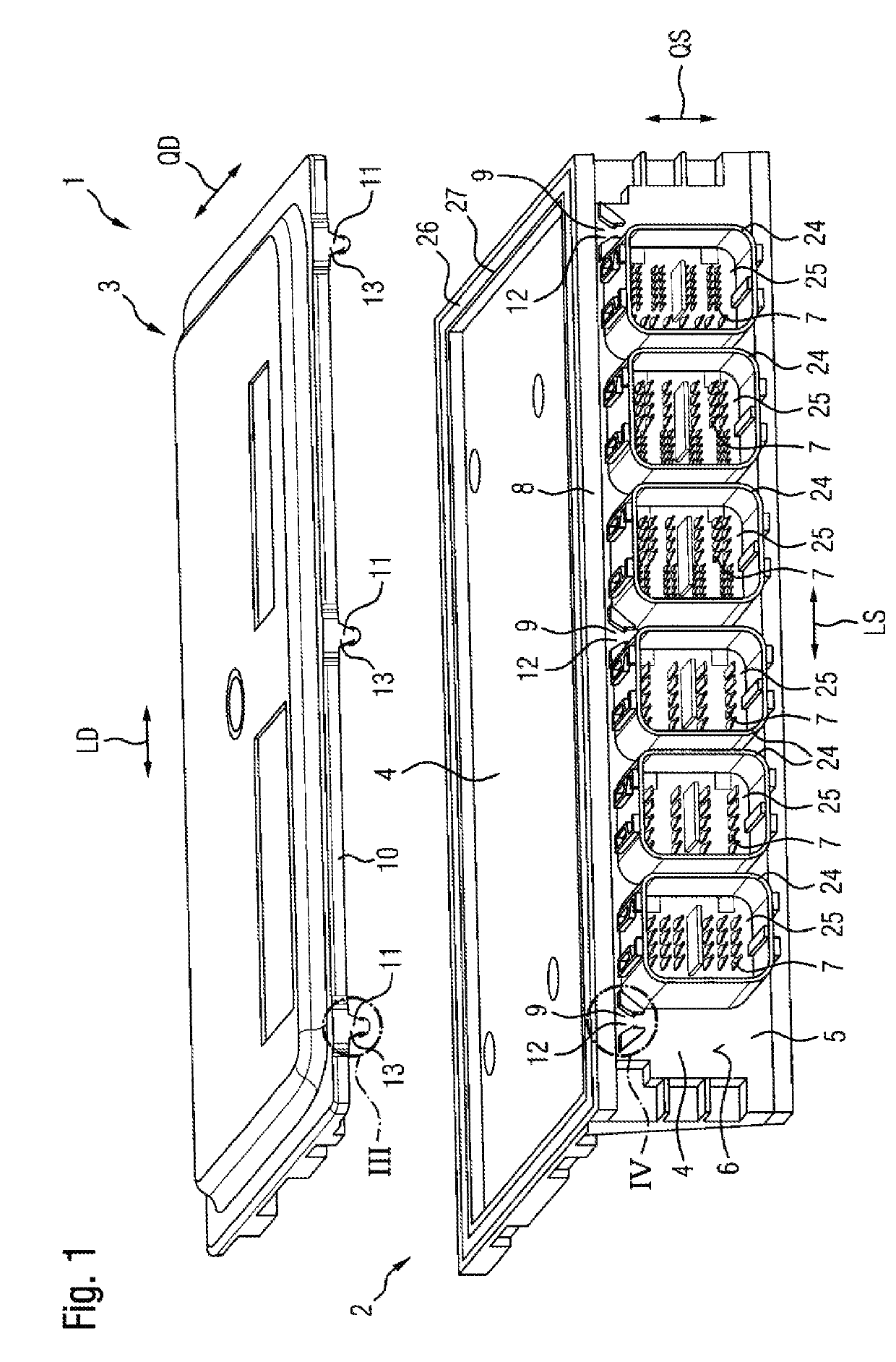
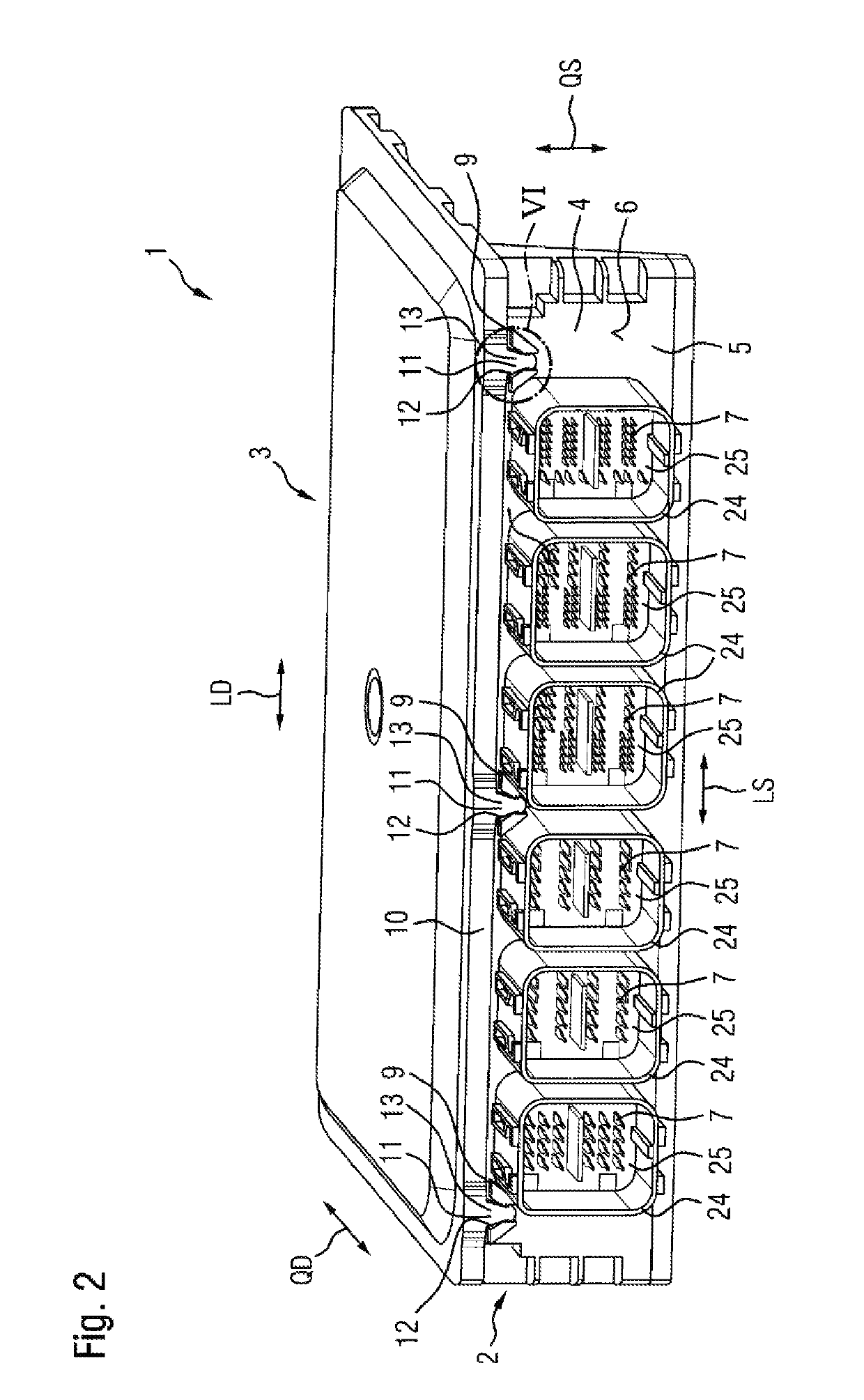
[0046]A combination 1 according to the invention and according to a first exemplary embodiment will be presented with reference to FIGS. 1 to 5. Said combination has a plug 2 and a cover 3 which is produced from sheet metal in the example.

[0047]The plug 2 has a plug housing 4 which has a plug main body 5 with a planar end face 6. In addition, the plug 2 has contact pins 7 which extend beyond the end face 6 at the front and in this way define a plug-in direction in which a mating plug (not illustrated in the figures) can be plugged onto the contact pins 7.

[0048]The plug housing 4 extends perpendicularly in relation to the plug-in direction in a plug longitudinal direction LS and in a plug transverse direction QS which is perpendicular in relation to the plug longitudinal direction LS and in relation to the plug-in direction. Said plug housing has a plug longitudinal edge 8 which extends along the plug longitudinal direction LS. In the selected example, three insertion receptacles 9 w...


PUM


Abstract

A combination of a plug and a cover. The plug has a plug housing and a plug longitudinal edge which extends along a plug longitudinal direction and on which at least one insertion receptacle is arranged which borders a receiving opening. The cover has a cover longitudinal edge in the cover longitudinal direction and on which at least one insertion element for insertion into the receiving opening is arranged. The insertion element has a shaft and at least one holding projection which proceeds from the shaft. The insertion receptacle has two wall regions which delimit the receiving opening on two opposite sides. In a non-assembled state of the plug and the cover, in at least one perpendicular cross-sectional plane, an opening width between the two wall regions is smaller than a width of the insertion element in a cross-sectional plane which is perpendicular in relation to the element plug-in direction.

Description

TECHNICAL FIELD[0001]The invention relates to a combination of a plug and a cover. The plug has a plug housing, which has a plug main body, and contact pins, which protrude beyond an end face of the plug main body. The plug housing extends in a plug longitudinal direction and in a plug transverse direction, which is perpendicular to said plug longitudinal direction, and has a plug longitudinal edge which extends along the plug longitudinal direction and on which or adjacent to which, on the plug housing, at least one insertion receptacle is arranged. The insertion receptacle borders a receiving opening. The cover extends in a cover longitudinal direction and in a cover transverse direction, which is perpendicular to said cover longitudinal direction, and has a cover longitudinal edge which extends along the cover longitudinal direction and on which or adjacent to which, on the cover, at least one insertion element for insertion into the receiving opening is arranged, which insertion...

Claims


Application Information

Patent Timeline
Patent Type & Authority Applications(United States)
IPC IPC(8): H05K5/00
CPCH05K5/0052H05K5/0069
Inventor REICHERT, MARTIN
Owner VITESCO TECH GERMANY GMBH
Why Eureka
Try Eureka