

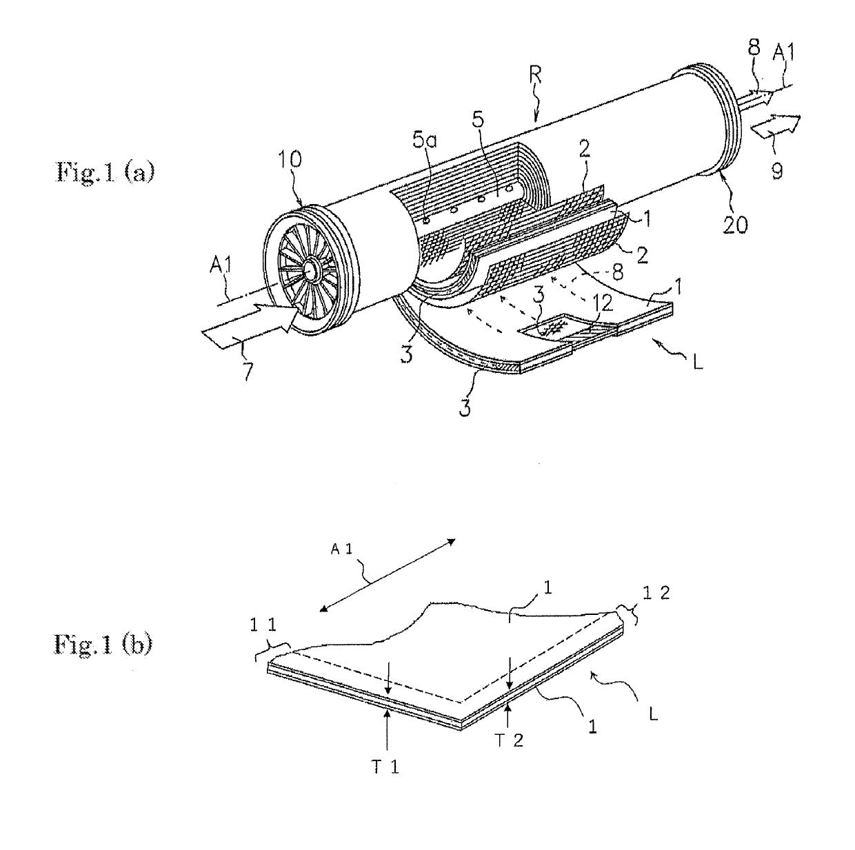
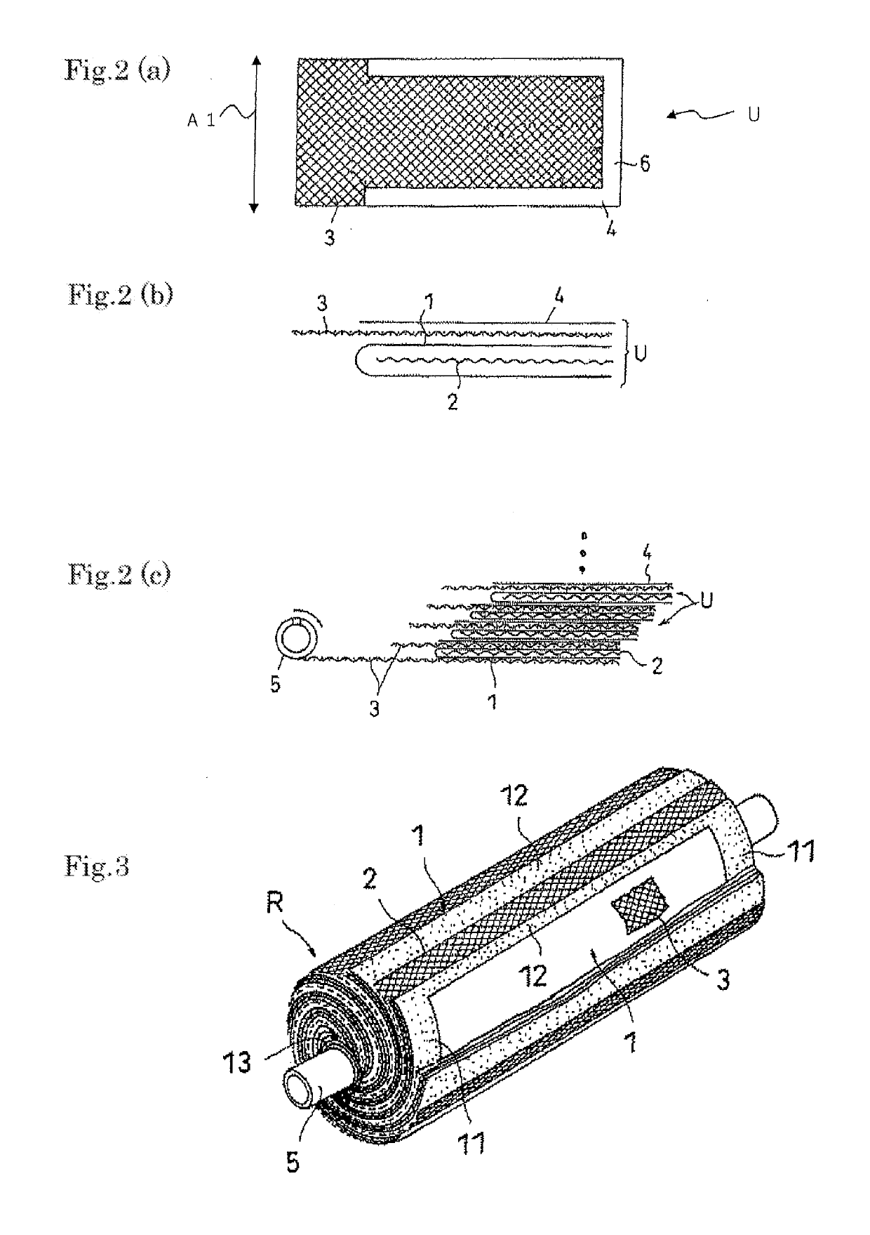
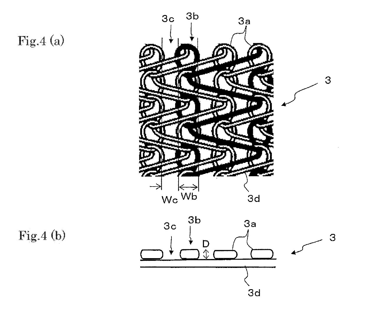
Spiral membrane element
a membrane element and spiral technology, applied in the field of spiral membrane elements, can solve the problems of increasing reducing and not being expected, so as to reduce the amount of permeation water, reduce the pressure loss of the membrane element, and reduce the operation energy of the membrane element.
- Summary
- Abstract
- Description
- Claims
- Application Information
AI Technical Summary
Benefits of technology
Problems solved by technology
Method used
Image

Examples
production example 1 (
Composite Semipermeable Membrane A; Thickness: 130 μm)
[0119]While a commercially available nonwoven fabric (width: about 1 m; density: 0.8 g / cm3) made of a polyester for water-treatment-membrane support and having a thickness of 100 μm was transported, a mixed solution of polysulfone and dimethylformamide (polymer concentration: 18.35% by weight) was continuously applied onto a surface of the fabric. The resultant was subjected to solidifying treatment in water of 35° C. temperature to produce a long porous support (thickness: 130 μm) in which a polymer porous layer of 30 μm thickness was formed.
[0120]While this porous support was transported, a solution A was brought into contact with the polymer porous layer outer-surface, this solution being a solution in which 3% by weight of m-phenylenediamine was mixed with 0.15% by weight of sodium laurylsulfate. An excess of the solution A was then removed to form a coating layer of the solution A. Next, a solution B was brought into contact...
production example 2 (
Production of Composite Semipermeable Membrane B; Thickness: 90 μm)
[0121]While a commercially available nonwoven fabric (width: about 1 m; density: 0.9 g / cm3) made of a polyester for water-treatment-membrane support and having a thickness of 65 μm was transported, a mixed solution of polysulfone and dimethylformamide (polymer concentration: 18.35% by weight) was continuously applied onto a surface of the fabric. The resultant was subjected to solidifying treatment in water of 35° C. temperature to produce a long porous support (thickness: 90 μm) in which a polymer porous layer of 25 μm thickness was formed.
[0122]While this porous support was transported, a solution A was brought into contact with the polymer porous layer outer-surface, this solution being a solution in which 3% by weight of m-phenylenediamine was mixed with 0.15% by weight of sodium laurylsulfate. An excess of the solution A was then removed to form a coating layer of the solution A. Next, a solution B was brought i...
production example 3 (
Composite Semipermeable Membrane C; Thickness: 80 μm)
[0123]While a commercially available nonwoven fabric (width: 1 mm; density: 0.9 g / cm3) made of a polyester for water-treatment-membrane support and having a thickness of 60 μm was transported, a mixed solution of polysulfone and dimethylformamide (polymer concentration: 18.35% by weight) was continuously applied onto a surface of the fabric. The resultant was subjected to solidifying treatment in water of 35° C. temperature to produce a long porous support (thickness: 80 μm) in which a polymer porous layer of 20 μm thickness was formed.
[0124]While this porous support was transported, a solution A was brought into contact with the polymer porous layer outer-surface, this solution being a solution in which 3% by weight of m-phenylenediamine was mixed with 0.15% by weight of sodium laurylsulfate. An excess of the solution A was then removed to form a coating layer of the solution A. Next, a solution B was brought into contact with th...
PUM
| Property | Measurement | Unit |
|---|---|---|
| thicknesses | aaaaa | aaaaa |
| thickness | aaaaa | aaaaa |
| thickness | aaaaa | aaaaa |
Abstract
Description
Claims
Application Information