Supercharge Your Innovation With Domain-Expert AI Agents!

Floating membrane reservoir system

a technology of floating membrane and reservoir system, which is applied in water-power plants, special-purpose vessels, machines/engines, etc., can solve the problems of reducing the construction and development timelines of alternative reservoir systems, and achieves the effects of reducing environmental impacts, improving aesthetics and social acceptability, and maintaining structural stability

Active Publication Date: 2019-08-22
UT BATTELLE LLC
View PDF4 Cites 0 Cited by
  • Summary
  • Abstract
  • Description
  • Claims
  • Application Information

AI Technical Summary

Benefits of technology

The patent describes a modular floating membrane reservoir system that can be used in a closed-loop pumped storage hydroelectric power system. This system is stable, light-weight, easy to install and pre-constructed, leading to reduced project construction and development timelines. It is also environmentally friendly and aesthetically acceptable. The system can achieve the same storage capacity as traditional reservoirs but with a smaller footprint. Overall, this innovative design provides a transportable, modular, scalable, and affordable solution for hydropower systems.

Problems solved by technology

In addition, the modular floating membrane reservoir system can lead to reduced project construction and development timelines relative to alternative reservoir systems.

Method used


Image

  • Floating membrane reservoir system
  • Floating membrane reservoir system
  • Floating membrane reservoir system

Examples


Embodiment Construction

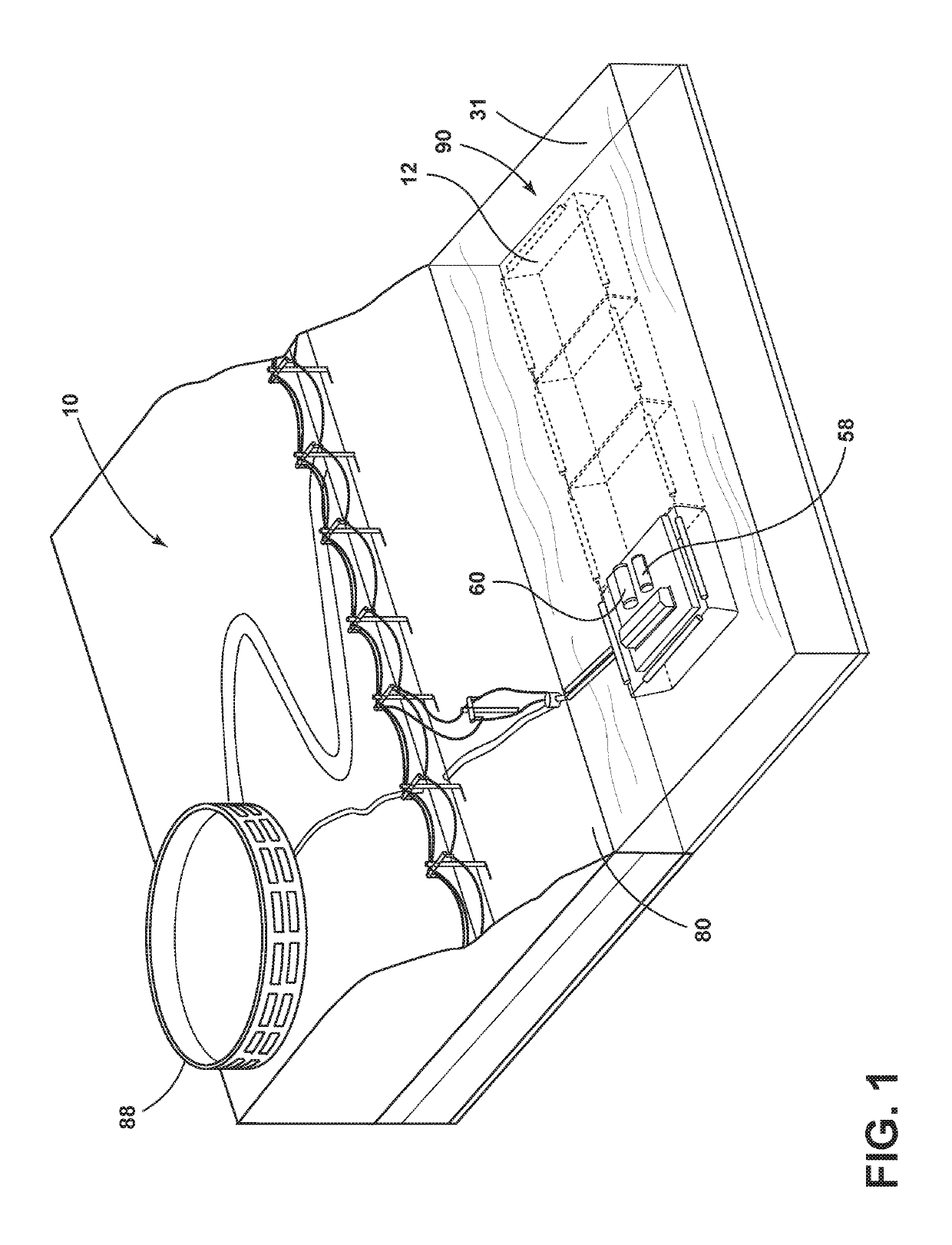
[0020]Referring to FIG. 1, a closed-loop pumped storage hydroelectric power system is illustrated and generally designated 10. FIG. 1 represents a potential application of a modular floating membrane reservoir system 12 for use as a lower reservoir in a closed-loop pumped storage hydroelectric power system. Alternatively, the floating reservoir 12 could be used as an upper reservoir or for both an upper reservoir and a lower reservoir. In the current embodiment, the modular floating membrane reservoir system 12 includes a flexible membrane 14, a system of pontoons 16, a floating walkway structure 18, and a structural support 20. Each such feature of the modular floating membrane reservoir system 12 is described below.

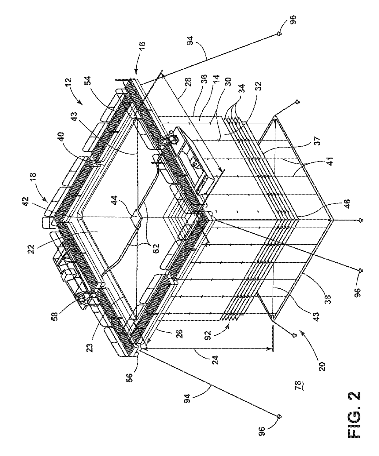
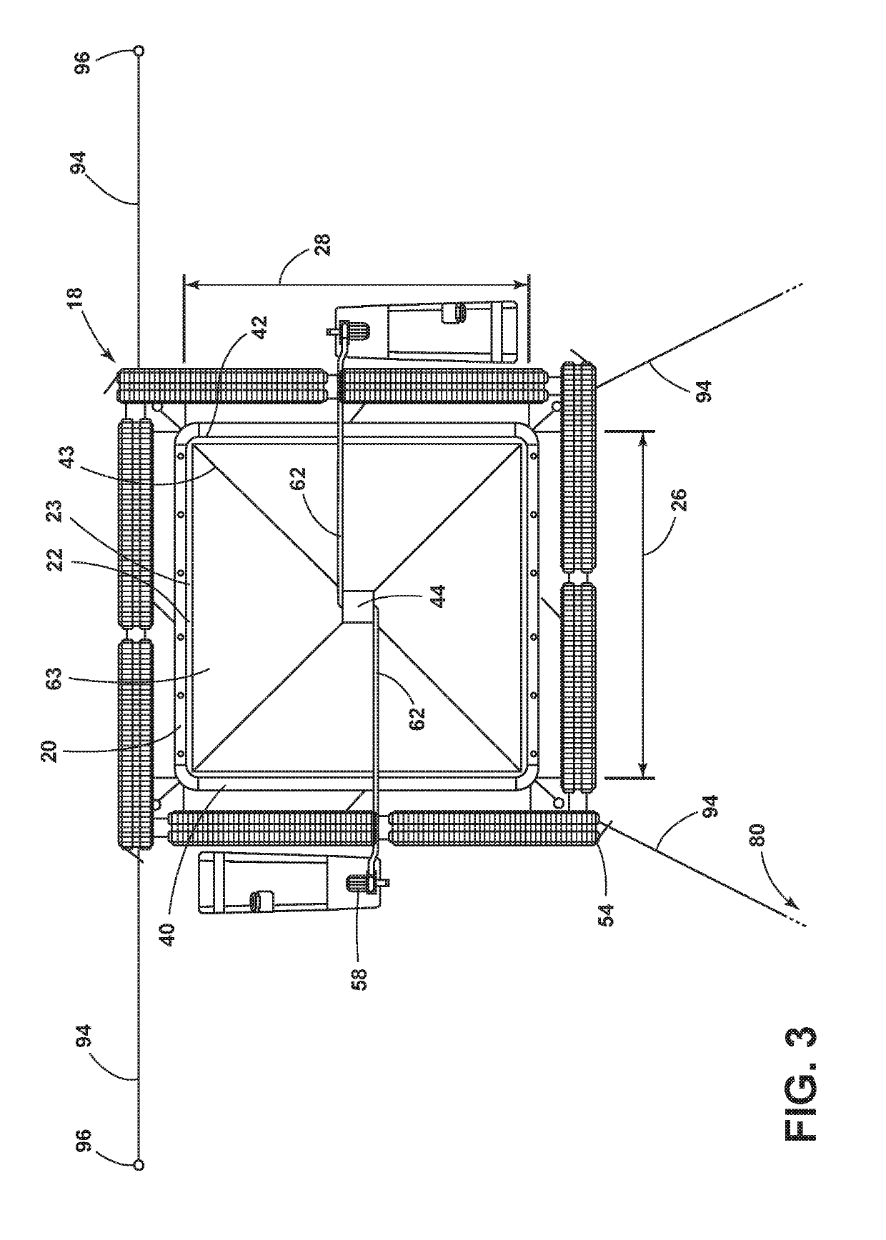
[0021]Referring to FIG. 2, the flexible membranes 14 defines a reservoir cell 22. The reservoir cell 12 includes a variable volumetric capacity for carrying fluid and may define any of a number of shapes including cuboid, as depicted in FIGS. 2 and 10. The reservoir cel...


PUM


Abstract

An improved system and method of storing water for a closed-loop pumped storage hydroelectric system is provided. The method includes providing a floating reservoir, positioning the floating reservoir in a waterbody, loading the floating reservoir with a volume of water from a source other than the surrounding waterbody, and transferring water from within the floating reservoir to an upper or lower reservoir of a pumped storage hydroelectric system. The floating reservoir includes a flexible membrane defining one or more reservoir cells including a vertically collapsible sidewall, such that each reservoir cell defines a depth varying in proportion to its internal volume of water. Each reservoir cell is buoyed by pontoons adjacent an outer periphery of the reservoir cell and is anchored to the shore or streambed.

Description

CROSS-REFERENCE TO RELATED APPLICATIONS[0001]This application claims the benefit of U.S. Provisional Application No. 62 / 631,529, filed on Feb. 16, 2018, and U.S. Provisional Application 62 / 683,052, filed on Jun. 11, 2018, the disclosures of which are hereby incorporated by reference in their entirety.STATEMENT REGARDING FEDERALLY SPONSORED RESEARCH[0002]This invention was made with government support under Contract No. DE-AC05-00OR22725 awarded by the U.S. Department of Energy. The government has certain rights in the invention.FIELD OF THE INVENTION[0003]The present invention relates to closed-loop pumped storage hydroelectric power systems and methods for using the same.BACKGROUND OF THE INVENTION[0004]An ongoing challenge in the energy industry, and particularly in the renewable energy industry, is how best to address fluctuations both in energy demand and energy production over time. One means of addressing this challenge is using pumped storage hydroelectricity. Pumped storage ...

Claims


Application Information

Patent Timeline
IPC IPC(8): B63B35/28B63B38/00E02B9/00
CPCB63B35/285B63B38/00E02B9/00B63B2735/00B63B35/00F03B13/06F05B2240/40F05B2240/93F05B2250/02F05B2250/23Y02E10/20Y02E60/16
Inventor HADJERIOUA, BOUALEM
Owner UT BATTELLE LLC
Features
  • R&D
  • Intellectual Property
  • Life Sciences
  • Materials
  • Tech Scout
  • Unparalleled Data Quality
  • Higher Quality Content
  • 60% Fewer Hallucinations
Learn More