Aircraft, controller and control method of aircraft, and recording medium storing computer software program for controlling aircraft

a controller and aircraft technology, applied in the direction of vertical landing/take-off aircraft, process and machine control, instruments, etc., can solve the problem of increasing the number of crashes of vtol aircraft such as multicopters

Active Publication Date: 2019-08-22
SUZUKI HIDEO
View PDF0 Cites 16 Cited by
  • Summary
  • Abstract
  • Description
  • Claims
  • Application Information

AI Technical Summary

Benefits of technology

[0004]A first aspect of the present invention inheres in an aircraft configured to take-off and land vertically, encompassing (a) a main-body, in which a gravity center is defined in a planer pattern, (b) a frame-structure configured to support the main-body, generating lifts in a same direction independently in each of a plurality of divided regions, which are defined around the gravity center, (c) a plurality of main rotors rotating around corresponding first rotation shafts, respectively, each of the main rotors is provided to the frame-structure, being assigned in each of the plurality of divided regions, (d) a plurality of auxiliary rotors rotating around corresponding second rotation shafts, respectively, each of the second rotation shafts is provided to the frame-structure and is rotated by a power-drive system independent from a power-drive system for the first rotation shaft, in each divided regions selected f

Problems solved by technology

However, as the multicopter spreads rapidly, the number of

Method used


Image

  • Aircraft, controller and control method of aircraft, and recording medium storing computer software program for controlling aircraft
  • Aircraft, controller and control method of aircraft, and recording medium storing computer software program for controlling aircraft
  • Aircraft, controller and control method of aircraft, and recording medium storing computer software program for controlling aircraft

Examples


first embodiment

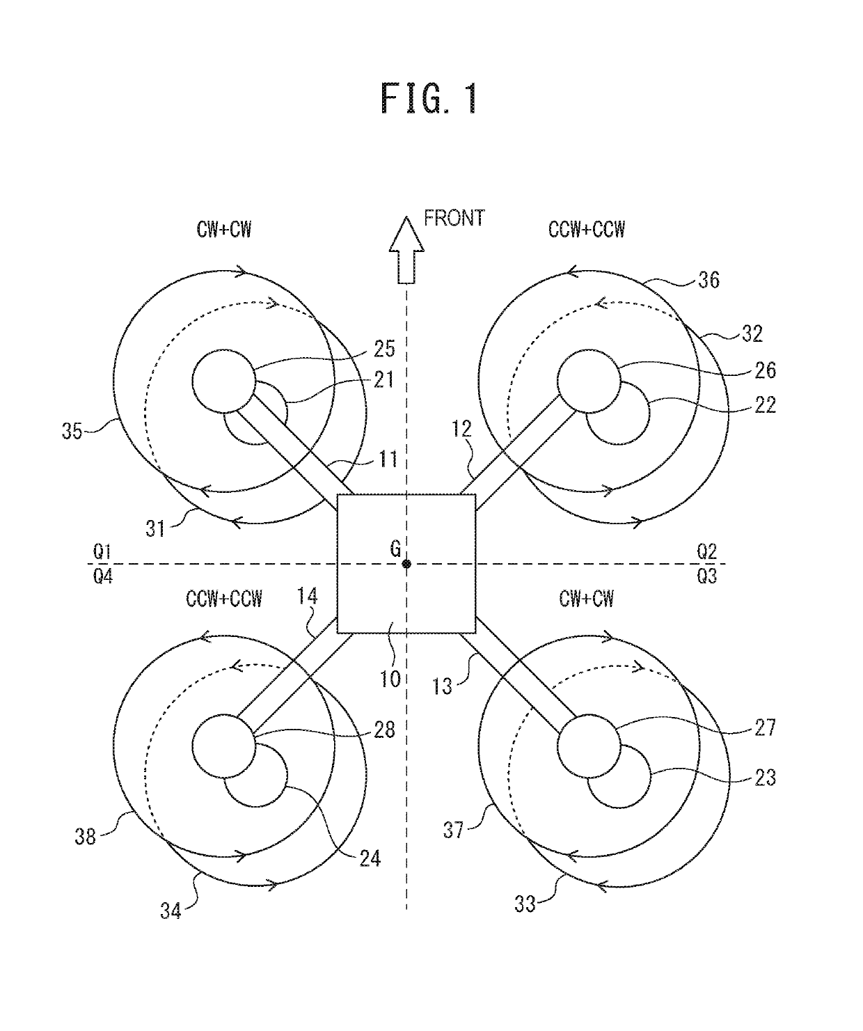
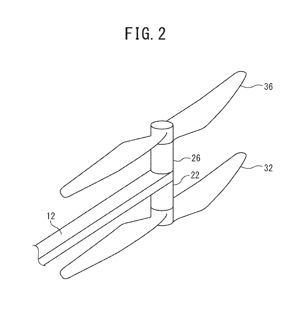
[0092]As illustrated in FIG. 1, an aircraft according to a first embodiment of the present invention is an octocopter, which is classified as a VTOL aircraft. The aircraft according to the first embodiment includes a main-body 10, a frame-structure (11, 12, 13 and 14) configured to support the main-body 10 disposed at a center of the frame-structure (11 to 14), and eight rotors (propellers) 31, 32, . . . , and 38 arranged to the frame-structure (11 to 14). In a planer pattern, a gravity center G, or a quadrant center G, is defined in the inside of the main-body 10. The frame-structure (11 to 14) supports the main-body 10 so as to generate a plurality of lifts in the same direction independently in each of a first divided region (quadrant) Q1, a second divided region (quadrant) Q2, a third divided region (quadrant) Q3, and a fourth divided region (quadrant) Q4, which surround the gravity center G. Each of the rotors 31 to 38 rotates in a direction of generating an upward lift. Note t...

first modification

[0163]On the right side of FIG. 12 a flight-state chart of an aircraft according to a first modification of the first embodiment is represented. Although the aircraft according to the first modification is an octocopter, which is classified as the VTOL aircraft, is similar to that of the first embodiment described above in that a main-body 10A, a frame-structure (11A, 12A, . . . , and 18A) configured to support the main-body 10A at a center, and the eight rotors 31 to 38 arranged to the frame-structure (11A to 18A) are included, the structure of the frame-structure (11A to 18A) is different from the first embodiment in that the frame-structure (11A to 18A) includes eight beams 11A, 12A, . . . , and 18A. Each of the eight beams 11A, 12A, . . . , and 18A extends radially from the gravity center defined in the main-body 10A in a planer pattern. In addition, the structure of the aircraft according to the first modification is different from the first embodiment in that the rotors 31 to ...

second modification

[0169]As illustrated in FIG. 14 on the right side, an aircraft or a VTOL aircraft according to a second modification of the first embodiment is different from the first embodiment and the first modification of the first embodiment described above in that a substantially H-shaped frame-structure (11B and 12B) is included in a planer pattern. The configuration, operations, and technical effects that are not described in the second modification are the same as those disclosed in the first embodiment and the first modification described above, and overlapping description is omitted.

[0170]The frame-structure (11B and 12B) includes a first beam 11B extending from the first quadrant Q1 to the fourth quadrant Q4 and a second beam 12B extending from the second quadrant Q2 to the third quadrant Q3 in parallel to the first beam 11B. A central main-body 10B is supported by the frame-structure (11B and 12B) between the first beam 11B and the second beam 12B. The main rotor 31, the auxiliary roto...


PUM


Abstract

An aircraft encompasses a main-body, a frame-structure to support the main-body, main and auxiliary rotors provided to the frame-structure and a controller for controlling rotations of the main and auxiliary rotors. In a first mode, the controller delivers a same control signal for rotating the set of the main and auxiliary rotors, and when one of the main and auxiliary rotors becomes abnormal, the controller delivers the same control signal for compensating a decrease of the lift. In a second mode, the controller delivers a control signal only to the normal rotor for increasing the rotation of the normal rotor. Sets of the main and auxiliary rotors in divided regions adjacent to a subject divided region are rotated in a direction counter to the subject divided region. By the first and second modes, the lifts are equalized for balancing the aircraft.

Description

CROSS REFERENCE TO RELATED APPLICATIONS AND INCORPORATION BY REFERENCE[0001]This application is a continuation application of International Application No. PCT / JP2017 / 039804, filed on Nov. 2, 2017 and claims benefit of priority under 35 USC 119 based on Japanese Patent Application No. P2016-226317 filed on Nov. 4, 2016, and PCT Application No. PCT / JP2017 / 024917 filed on Jul. 7, 2017, the entire contents of all of which are incorporated by reference herein.BACKGROUND OF THE INVENTION1. Field of the Invention[0002]The present invention relates to aircrafts including a vertical take-off and landing (VTOL) aircraft, a controller and a control method of the VTOL aircraft, and a recording medium storing computer software program for controlling the VTOL aircraft.2. Description of the Related Art[0003]A drone has been developed as an unmanned multicopter, and the governments of the various nations have been pursuing a policy such as formulating standards of license. However, as the multico...

Claims


Application Information

Patent Timeline
IPC IPC(8): B64C9/06B64D27/02B64C29/00B64C19/02B64C17/00
CPCB64C9/06B64D27/02B64C29/0016B64C19/02B64C17/00B64C2201/14B64D31/02G05D1/0858G05D1/0072B64U2201/00B64U10/13B64U30/20B64U50/19B64D27/24B64C27/08B64C39/02
Inventor SUZUKI, HIDEOSUZUKI, SACHIHIROMATSUSHITA, KOTAROHANADA, MASAKISHINOHARA, TORUNIIJIMA, NORIKONAKAMURA, TADAO
Owner SUZUKI HIDEO
Why Eureka
Try Eureka