
Power conversion circuit

a power conversion circuit and power conversion technology, applied in the direction of power conversion systems, electronic switching, pulse techniques, etc., can solve the problems of shortening the high-side switches, and reducing the service life of low-side switches b>3/b>, so as to reduce external noise, suppress the success of erroneous ignition, and stabilize the operation of power switching elements

Active Publication Date: 2019-08-22
PANASONIC INTELLECTUAL PROPERTY MANAGEMENT CO LTD
View PDF0 Cites 1 Cited by
  • Summary
  • Abstract
  • Description
  • Claims
  • Application Information

AI Technical Summary

Benefits of technology

The present invention provides a power conversion circuit that operates stably for a long period of time, even in the face of external noise. This is achieved through the use of a power switching element that is less affected by erroneous ignition, resulting in a reduction of through-currents and a prolonged lifespan for the power switching element. In summary, the technical effect of the present invention is to provide a circuit with less impact of external noise and stable operation for a long period of time.

Problems solved by technology

As a result, operation of low-side switch 3 is liable to become unstable.
This generates a through-current, thereby leading to shortage of a length of life of low-side switch 3 and high-side switch 7.

Method used


Image

  • Power conversion circuit
  • Power conversion circuit
  • Power conversion circuit

Examples


Embodiment Construction

[0018]An exemplary embodiment of the present invention will be described below with reference to the accompanying drawings.

Exemplary Embodiment

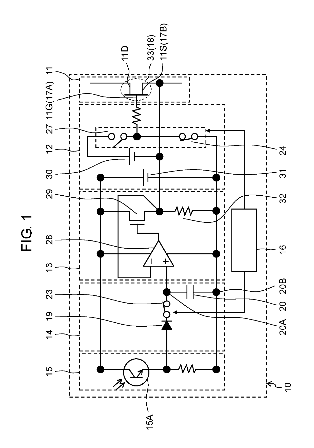
[0019]FIG. 1 is a circuit block diagram illustrating a configuration of power conversion circuit 10 according to an exemplary embodiment of the present invention.

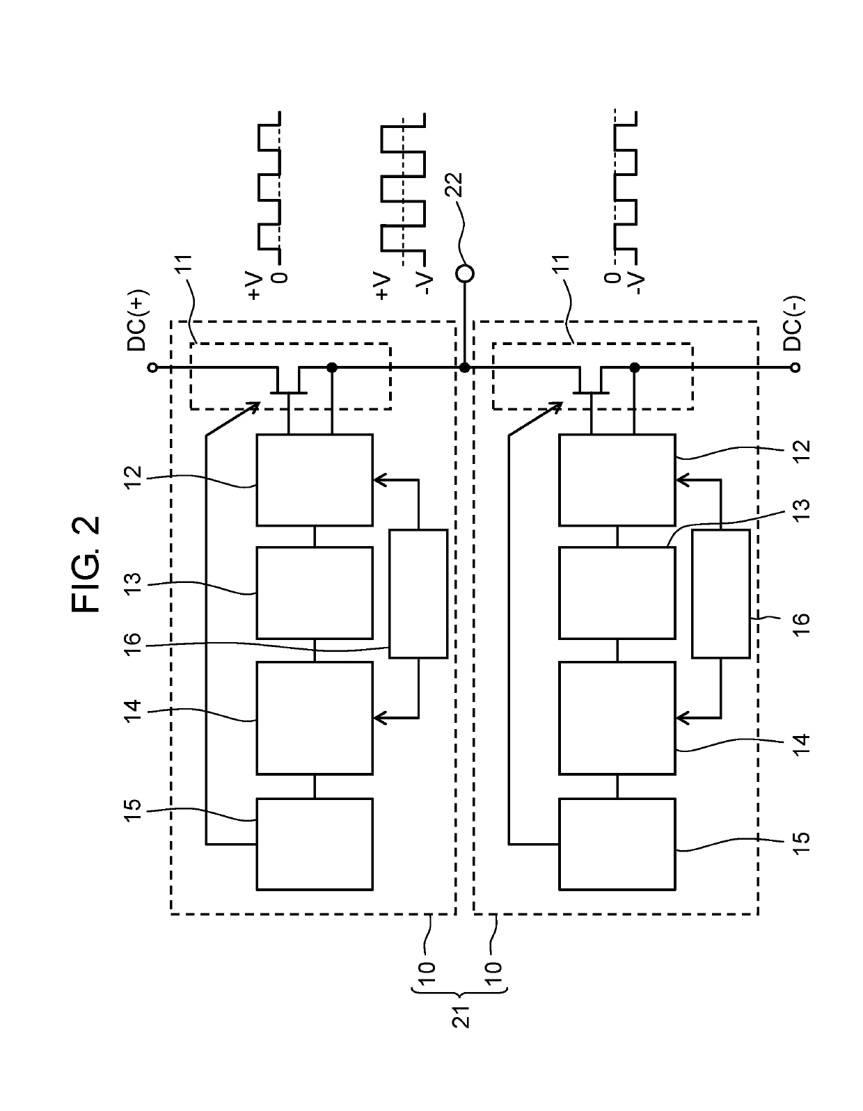
[0020]Power conversion circuit 10 includes control circuit 16, power switching element 11, driving circuit 12, light-receiving circuit 15, hold circuit 14, and comparison circuit 13.

[0021]Control circuit 16 alternately sends an OFF-level control signal (OFF signal) and an ON-level control signal (ON signal).

[0022]Power switching element 11 includes control terminal 17A, reference terminal 17B, and light-emitting part 18 that emits light in accordance with an energization current flowing through power switching element 11. In the present exemplary embodiment, power switching element 11 is a field-effect transistor that has control terminal 17A as gate terminal 11G and reference termin...


PUM


Abstract

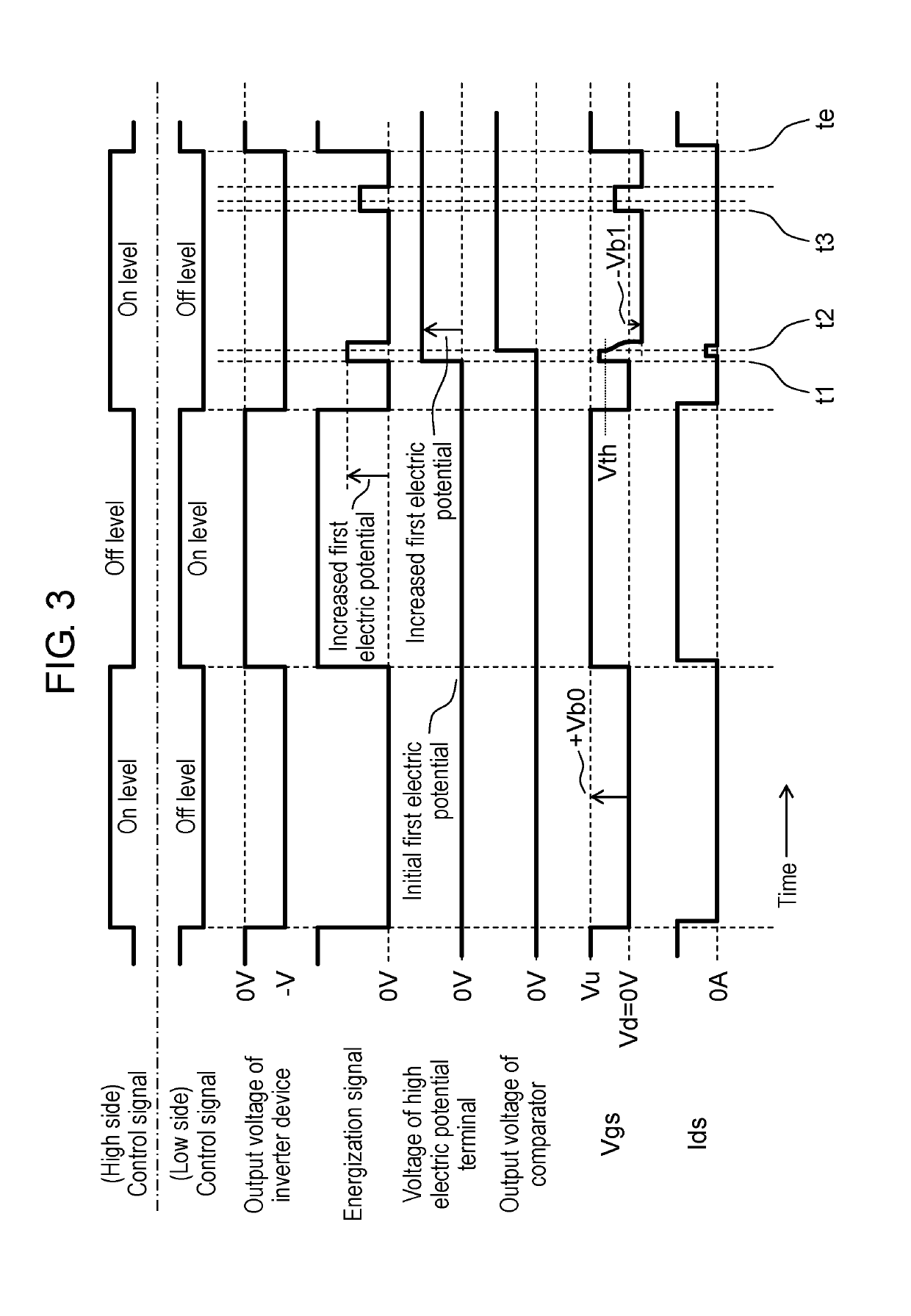
A light-receiving circuit receives light emitted by a light-emitting part and generates an energization signal that is an electric current based on intensity of the light. A hold circuit is configured to supply an electric charge of an energization signal to a high electric potential terminal and not to decrease a voltage of the high electric potential terminal in a case where a control circuit is sending an OFF signal. Furthermore, the hold circuit is configured not to supply the electric charge of the energization signal to the high electric potential terminal and to keep the voltage of the high electric potential terminal in a case where t e control circuit is sending an ON signal. A comparison circuit compares a comparison signal and a reference signal, generates a bias voltage based on a result of the comparison between the comparison signal and the reference signal, and feeds back the bias voltage as a reference signal. A driving circuit supplies the bias voltage to a reference terminal while the control circuit is sending the OFF signal.

Description

TECHNICAL FIELD[0001]The present invention relates to a power conversion circuit used for various electronic devices.BACKGROUND ART[0002]A conventional power conversion circuit will be described below with reference to the accompanying drawing. FIG. 5 is a circuit block diagram illustrating a configuration of power conversion device 2 using conventional power conversion circuit 1. Power conversion circuit 1 includes low-side switch 3, driving circuit 4, detection circuit 5, and switching circuit 6. Power conversion circuit 8 that includes high-side switch 7 is connected in parallel with power conversion circuit 1. FIG. 5 illustrates an example in which power conversion circuit 1 is disposed for use on a low side of power conversion device 2.[0003]In power conversion device 2, high-side switch 7 and low-side switch 3 alternately turn on and off, and thus power conversion circuit 8 and power conversion circuit 1 operate. As a result, output terminal 9 alternately outputs a positive el...

Claims


Application Information

Patent Timeline
IPC IPC(8): H02M7/537H02M1/08H03K17/16H03K17/687
CPCH02M7/537H02M1/08H03K17/16H03K17/687H02M2001/0009H02M7/5387H02M7/53871H02M7/003H03K17/785H03K17/165H02M1/0009
Inventor TAKANO, YOHKOHDA, SHINICHI
Owner PANASONIC INTELLECTUAL PROPERTY MANAGEMENT CO LTD
Learn More