
Prosthetic mitral valve with improved anchors and seal

a technology anchors, which is applied in the field of prosthetic mitral valves with improved anchors and seals, can solve the problems of reducing the efficiency of heart blood pumping, affecting the life of patients, and inhibiting the valves' ability to control blood flow

Active Publication Date: 2019-08-29
EDWARDS LIFESCIENCES CORP
View PDF0 Cites 49 Cited by
  • Summary
  • Abstract
  • Description
  • Claims
  • Application Information

AI Technical Summary

Benefits of technology

The patent describes a system and method for replacing a heart valve using a transseptal approach. The system allows for bending of the delivery system to steer the prosthesis from the septum to the native mitral valve. A capsule is used to contain the prosthesis for delivery. This technology allows for the delivery of implants to various locations within the heart, including the native mitral valve.

Problems solved by technology

Diseased heart valves exhibit impairments such as narrowing of the valve or regurgitation, which inhibit the valves' ability to control blood flow.
Such impairments reduce the heart's blood-pumping efficiency and can be a debilitating and life threatening condition.
For example, valve insufficiency can lead to conditions such as heart hypertrophy and dilation of the ventricle.
However, a problem occurs when blood flows around the valve on the outside of the prosthesis.
For example, in the context of replacement heart valves, paravalvular leakage has proven particularly challenging.
An additional challenge relates to the ability of such prostheses to be secured relative to intralumenal tissue, e.g., tissue within any body lumen or cavity, in an atraumatic manner.
Yet another challenge arises when trying to reduce the likelihood of thrombosis within parts of the replacement valves.
The stiffness improving material may not providing tension to the inner frame anchoring features when the prosthesis is in the compressed position.
The material may not provide tension to the inner frame anchoring features when the prosthesis is in the compressed position.

Method used


Image

  • Prosthetic mitral valve with improved anchors and seal
  • Prosthetic mitral valve with improved anchors and seal
  • Prosthetic mitral valve with improved anchors and seal

Examples


Embodiment Construction

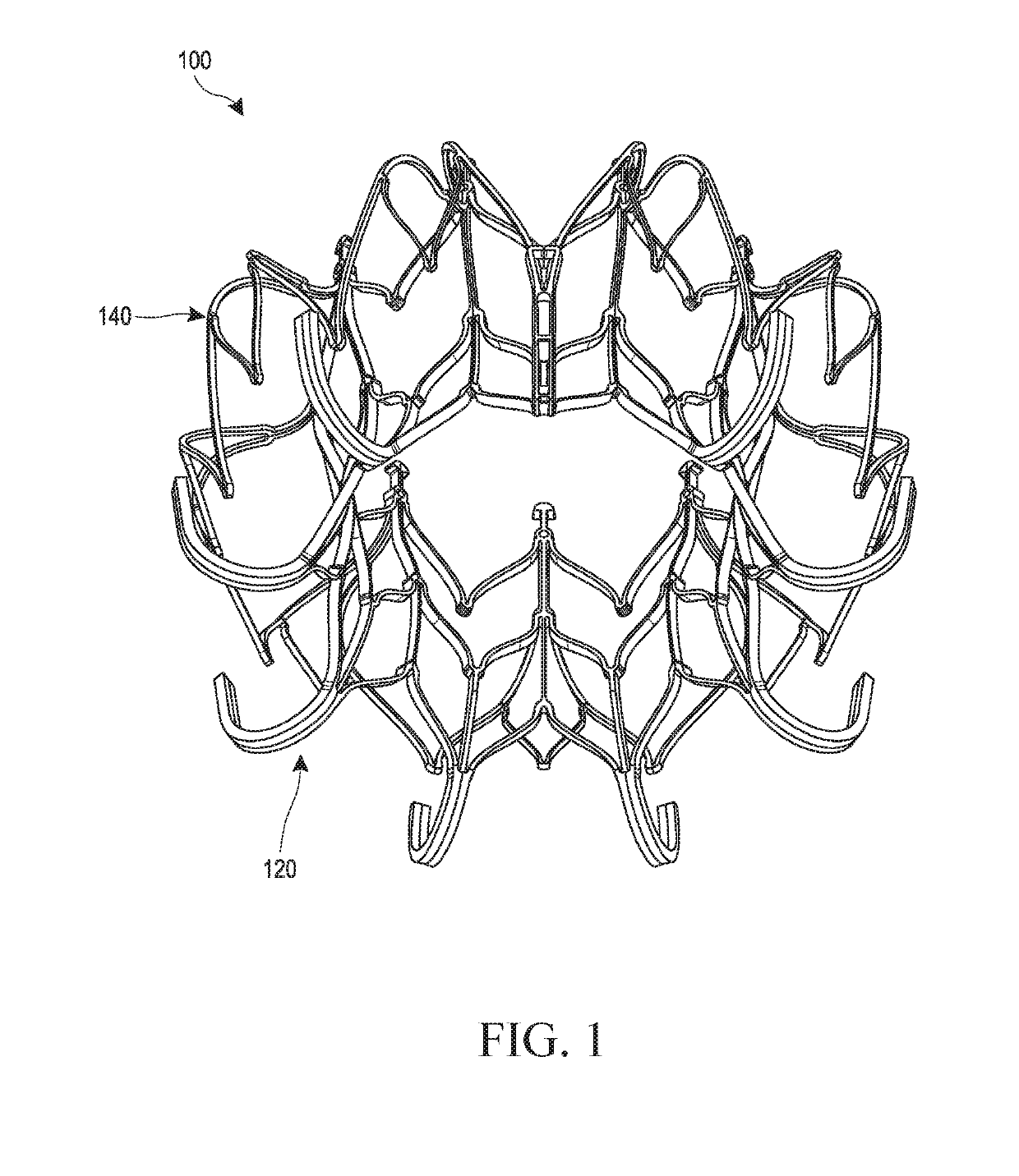
[0095]The present specification and drawings provide aspects and features of the disclosure in the context of several embodiments of prostheses, replacement heart valves, and methods that are configured for use in the vasculature of a patient, such as for replacement of natural heart valves in a patient. These embodiments may be discussed in connection with replacing specific valves such as the patient's mitral valve. However, it is to be understood that the features and concepts discussed herein can be applied to replacing other types of valves including, but not limited to, the aortic valve, the pulmonary valve, and the tricuspid valve. Moreover, it is to be understood that the features and concepts discussed herein can be applied to products other than heart valve implants. For example, the controlled positioning, deployment, and / or securing features described herein can be applied to medical implants, for example other types of expandable prostheses, for use elsewhere in the bod...


PUM


Abstract

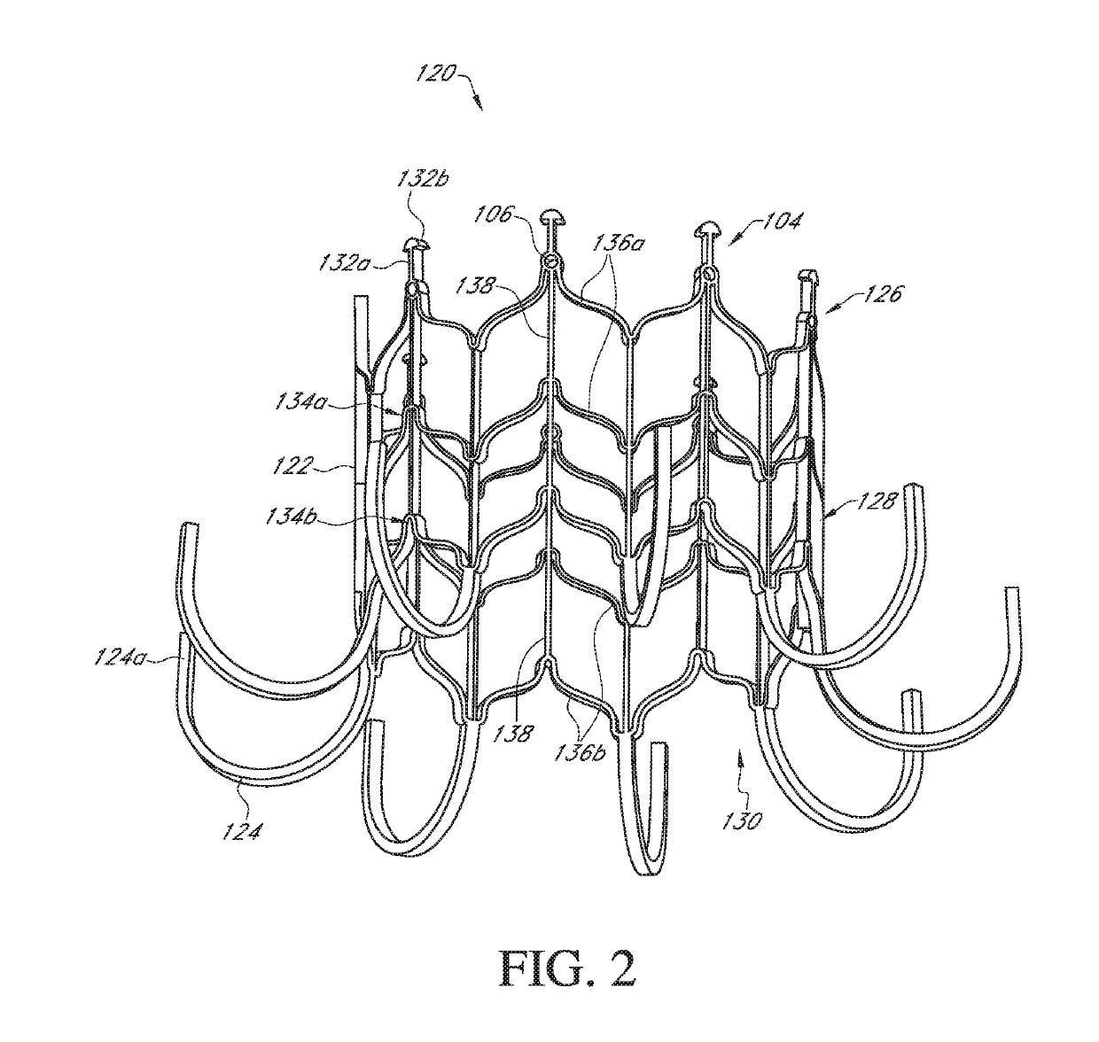
A mitral valve prosthesis includes an hourglass shaped inner frame and a bulbous outer frame. A valve body having a plurality of leaflets is positioned within an interior region of the inner frame. The leaflets are shaped to substantially conform to an interior surface of the inner frame when the leaflets are in an open position. As a result, the gap between the leaflets and the inner frame is decreased, thereby reducing the likelihood of thrombus formation. Ventricular anchors are preferably provided along a distal end of the inner frame. The anchors extend proximally for placement behind native mitral valve leaflets. A fabric skirt may extend along an inner or outer surface of the outer frame. In preferred embodiments, the fabric skirt extends distally beyond a distal end of the outer frame and is adapted for forming a seal along the mitral valve annulus.

Description

CROSS-REFERENCES TO RELATED APPLICATIONS[0001]This application claims the benefit of U.S. Provisional Application No. 62 / 781,817, filed Dec. 19, 2018, entitled “PROSTHETIC MITRAL VALVE WITH IMPROVED ANCHORS AND SEAL” and U.S. Provisional Application No. 62 / 636,672, filed Feb. 28, 2018, entitled “PROSTHETIC MITRAL VALVE WITH IMPROVED ANCHORS AND SEAL”, the entirety of each of which is hereby incorporated by reference.BACKGROUNDField[0002]Certain embodiments disclosed herein relate generally to prostheses for implantation within a lumen or body cavity. In particular, certain embodiments relate to expandable prostheses such as replacement heart valves, such as for the mitral valve, that are configured to be secured to intralumenal tissue and prevent paravalvular leakage.Description of the Related Art[0003]Human heart valves, which include the aortic, pulmonary, mitral and tricuspid valves, function essentially as one-way valves operating in synchronization with the pumping heart. The v...

Claims


Application Information

Patent Timeline
Patent Type & Authority Applications(United States)
IPC IPC(8): A61F2/24
CPCA61F2/2409A61F2/2418A61F2002/9505A61F2220/0008A61F2230/0093A61F2/2427A61F2220/0025A61F2230/001
Inventor COOPER, ALEXANDER H.SCHWARTZ, JULIET LAURAPHAM, WENDY VOLUONG, HIEU MINHSANCHEZ, JULIO CESARPETERSON, MATTHEW A.RATZ, J. BRENTAI, LISONG
Owner EDWARDS LIFESCIENCES CORP
Learn More