
Vehicle control device, vehicle control method, and storage medium

a vehicle control and vehicle control technology, applied in vehicle position/course/altitude control, process and machine control, instruments, etc., can solve the problems of inability to appropriately control the behavior of the vehicle, the shape of the road surface does not uniformly act on all the vehicle wheels, and the vehicle becomes unstable. the effect the reduction of the process of controlling the steering devi

Active Publication Date: 2019-08-29
HONDA MOTOR CO LTD
View PDF0 Cites 5 Cited by
  • Summary
  • Abstract
  • Description
  • Claims
  • Application Information

AI Technical Summary

Benefits of technology

The present invention provides a vehicle control device, method, and storage medium that can limit the impact of road surface shape on vehicle behavior. This is achieved by causing the vehicle to run on a stable road surface, reducing the process of steering device control. Additionally, by controlling the speed at which control is performed, the process of steering device control can be further reduced. The behavior of the vehicle can be further stabilized based on changes in road surface state, including narrow roads and road surfaces with predicted gradients. Overall, the invention improves the stability of vehicle behavior and reduces the impact of road surface shape on driving experience.

Problems solved by technology

However, according to conventional technologies, a side wind is detected, and a steering angle of a steering device is adjusted, and thus driving control in a case in which the behavior of a vehicle becomes unstable due to the shape of a road surface of a road is not taken into account.
However, the shape of a road surface does not uniformly act on all the vehicle wheels.
For this reason, even when conventional technologies are applied to changes in the road surface, there are cases in which the behavior of a vehicle cannot be appropriately controlled.

Method used


Image

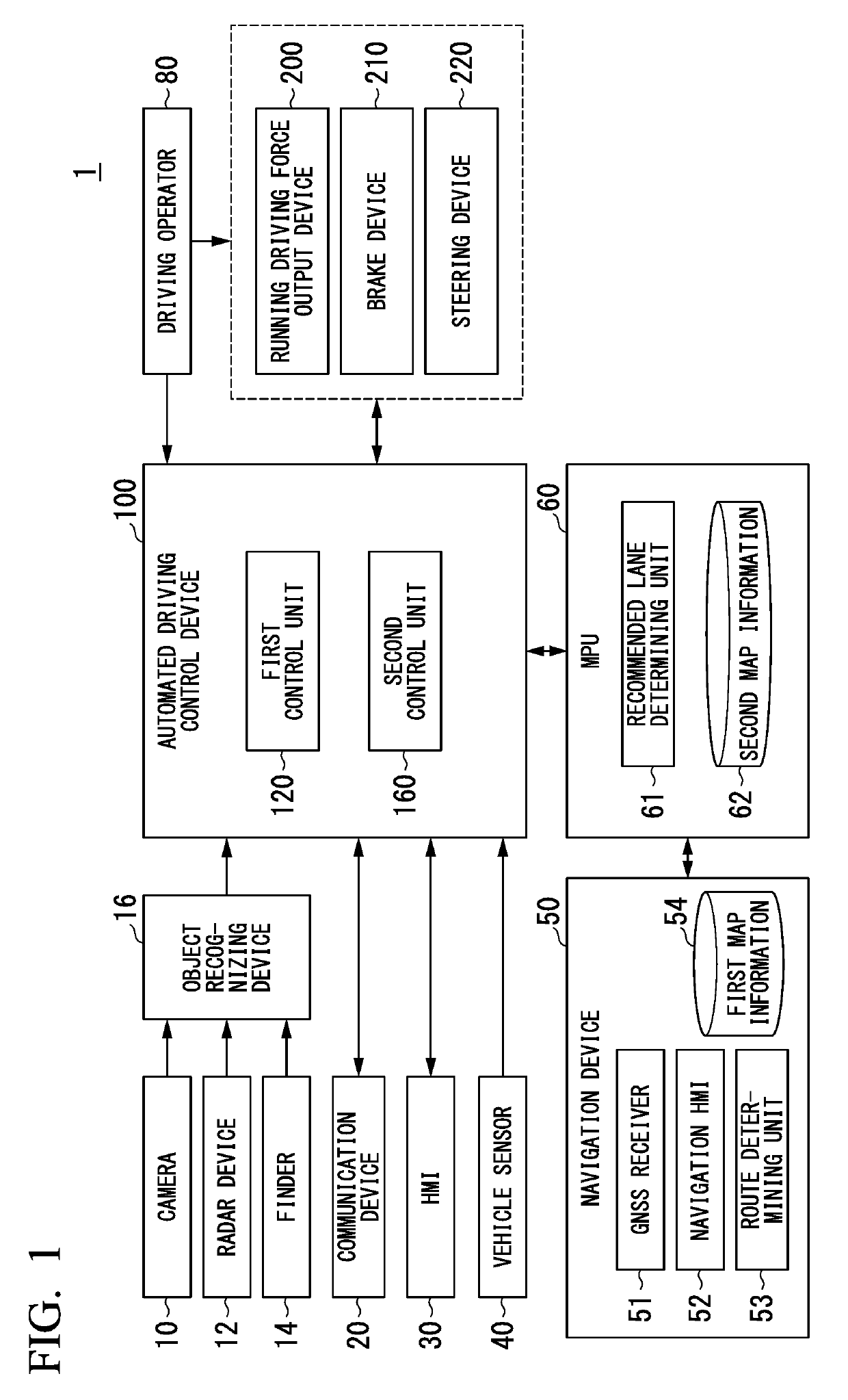
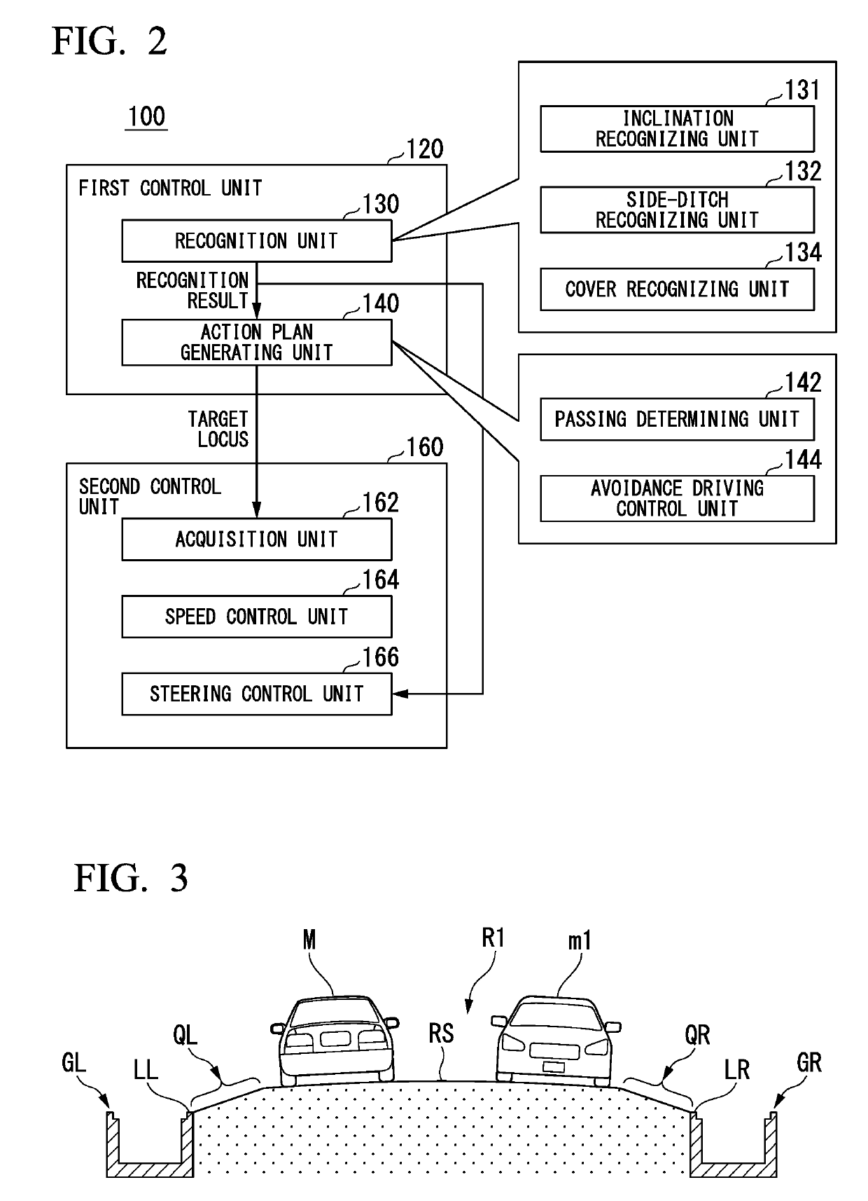
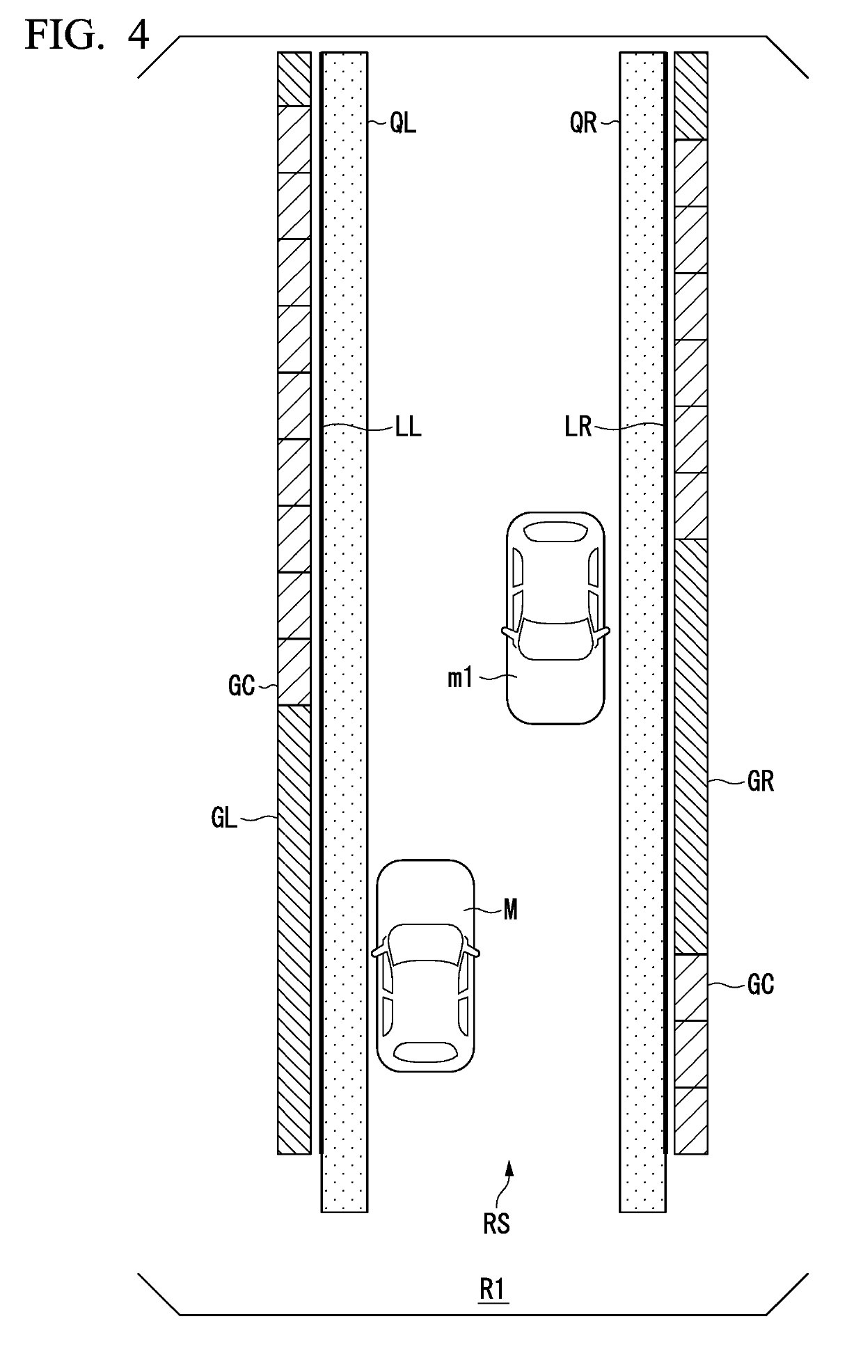
  • Vehicle control device, vehicle control method, and storage medium
  • Vehicle control device, vehicle control method, and storage medium
  • Vehicle control device, vehicle control method, and storage medium

Examples


case 1

[Other Case 1]

[0095]FIG. 7 is a diagram showing one example of a state in which a subject vehicle M passes through a cover of a side ditch. In a case in which it is determined that the subject vehicle M cannot pass another vehicle m1 by running in the road surface inclination area QL, the passing determining unit 142 determines whether or not the subject vehicle M can pass the another vehicle m1 by running on the cover GC of the side ditch GL disposed on the left side.

[0096]The passing determining unit 142, for example, calculates a runnable width W3 that is acquired by excluding a width occupied by the another vehicle m1 from a distance acquired by adding the width of the cover GC of the side ditch GL, the width of the road surface inclination area QL, and the width WRS of the flat part Rs, in the crossing direction of the road RE In the width of the cover GC of the side ditch GL, a width between the road surface inclination area QL and the flat part RS is also included. The passin...


PUM


Abstract

A vehicle control device (100) including a recognition unit (130) that that is configured to recognize a peripheral situation of a vehicle and a driving control unit (140, 166) that that is configured to control at least steering of the vehicle on the basis of a result of recognition acquired by the recognition unit, and, in a case in which the recognition unit is configured to recognize a road surface inclination area in which a gradient toward a lower side in a vertical direction is formed from a flat part of the road toward a road end, which is disposed at the road end of an advancement direction of the vehicle, and the vehicle is running on the road surface inclination area, the driving control unit is configured to adjust a steering angle of the vehicle in a direction in which the vehicle is away from the road end on a side on which the road surface inclination area is present.

Description

CROSS-REFERENCE TO RELATED APPLICATION[0001]Priority is claimed on Japanese Patent Application No. 2018-032261, filed Feb. 26, 2018, the content of which is incorporated herein by reference.BACKGROUNDField of the Invention[0002]The present invention relates to a vehicle control device, a vehicle control method, and a storage medium.Description of Related Art[0003]In recent years, automated control of vehicles has been researched. In relation to this, technologies for detecting a cross wind blown on a vehicle using a sensor and correcting a locus along which the vehicle runs by controlling a steering angle of a steering device on the basis of a detected result are known (for example, see Japanese Utility Patent Publication No. S62-037582).SUMMARY[0004]However, according to conventional technologies, a side wind is detected, and a steering angle of a steering device is adjusted, and thus driving control in a case in which the behavior of a vehicle becomes unstable due to the shape of ...

Claims


Application Information

Patent Timeline
Patent Type & Authority Applications(United States)
IPC IPC(8): B60W30/02B62D15/02G06K9/00
CPCB60W30/02B62D15/025G06K9/00791B60W2550/12G05D1/0257B60W2710/207G05D1/0214G05D1/0231B60W2550/143B60W10/20B60W30/09B60W40/076B60W40/06G05D1/0088B60W2555/20B60W2552/20G06V20/588G06V20/56
Inventor MATSUNAGA, HIDEKIOSHITANI, YUKI
Owner HONDA MOTOR CO LTD
Learn More