Thermally stable flexible lighting device

a flexible, lighting technology, applied in semiconductor devices, lighting and heating apparatus, instruments, etc., can solve the problems of increasing the risk of mechanical failure, and achieve the effect of mechanical stability, good optical coupling, and good optical coupling

Active Publication Date: 2019-09-12
LUMILEDS
View PDF3 Cites 2 Cited by
  • Summary
  • Abstract
  • Description
  • Claims
  • Application Information

AI Technical Summary

Benefits of technology

[0009]The lighting device according to the invention further comprises a bendable light guide arranged to guide light emitted from the LED element. A light guide is understood to be a solid element of light transmitting material, which guides light internally. While the material is preferably transparent, this may also comprise translucent materials e.g. with optically diffusive properties. Light traversing the interior of the light guide may, in some cases, undergo total internal reflection at boundary surfaces, however this is not a requirement. The light guide is bendable, i.e. the light guide and preferably the entire lighting device may be bent, e.g. to conform to the contour of a part on which the light guide and / or the lighting device is mounted. Preferably, the light guide is disposed such that it may be bent at least in one bending direction to a bending radius of below 5 meters, preferably below 3 meters, most preferably 1 m or below. In order to achieve a bendable light guide, it is at least partly made of elastic material(s). The term “elastic” may e.g. be understood to denote materials with a modulus of elasticity (Young's modulus) of below 5 GPa, preferably at or below 1 GPa, particularly preferably 0.3 GPa or below. A preferred material for the first light guide is Silicone, e.g. with a Young's modulus of below 0.1 GPa.
[0010]According to the invention, the light guide comprises at least two separate portions. A first portion of the light guide is formed of an elastic light transmitting light guide material and covers at least the emission direction of the LED element. Preferably, the first portion of the light guide contacts the LED element in the emission direction. This allows good optical coupling. Particularly preferably the LED element is at least partially embedded within the light guide material of the first light guide portion, which ensures both good optical coupling and mechanically stable connection, in particular in the preferred case of an unpackaged LED element.
[0011]According to the invention, the lighting device further includes a second portion of the light guide, which may be made of the same elastic light transmitting material as the first portion, in particular silicone, or of a different material. The second portion of the light guide is arranged spaced from the first portion in the emission direction by a separation space. The separation space arranged between the first and second light guide portion may be filled with a solid or liquid material of optical properties different from those of the light guide material, but preferably is free space, i.e. evacuated or filled with a gas, in particular air.
[0012]Light emitted from the LED element and guided by the first portion of the light guide may traverse the separation space to be further guided by the second portion of the light guide.
[0013]The separation space serves to mechanically decouple the first and second portions of the light guide. Both portions are separately affected by shrinkage or expansion due to temperature changes, according to their individual volume. As the first light guide portion arranged at the LED element constitutes only a fraction of the total volume of the light guide, separation of the two portions can limit the effect of thermal changes acting on the LED element. Generally, while the lighting device may have a small thickness (or height), a certain length of the optical path, i.e. distance between the LED element and a light emitting surface, is preferred to allow light spreading and uniformity on the light emitting surface.
[0014]In a preferred embodiment, the first and second portion of the light guide are connected by a deformable spring structure. The spring structure may serve to mechanically connect the first and second light guide portion, however not in a rigid manner, but allowing the relative arrangement of the two portions to vary by deformation of the spring structure. This may e.g. include different types of relative movement of the two light guide portions, such as e.g. tilting, shifting etc. Preferably, by deformation of the spring structure, the distance between the first and second light guide portions and thus the width of the separation space may vary. In particular, it is preferred that the spring structure is deformable to achieve a variable length in the emission direction.

Problems solved by technology

The inventors have concluded that temperature changes may lead to significant mechanical stress and thus increase the risk of mechanical failure.

Method used


Image

  • Thermally stable flexible lighting device
  • Thermally stable flexible lighting device
  • Thermally stable flexible lighting device

Examples


Embodiment Construction

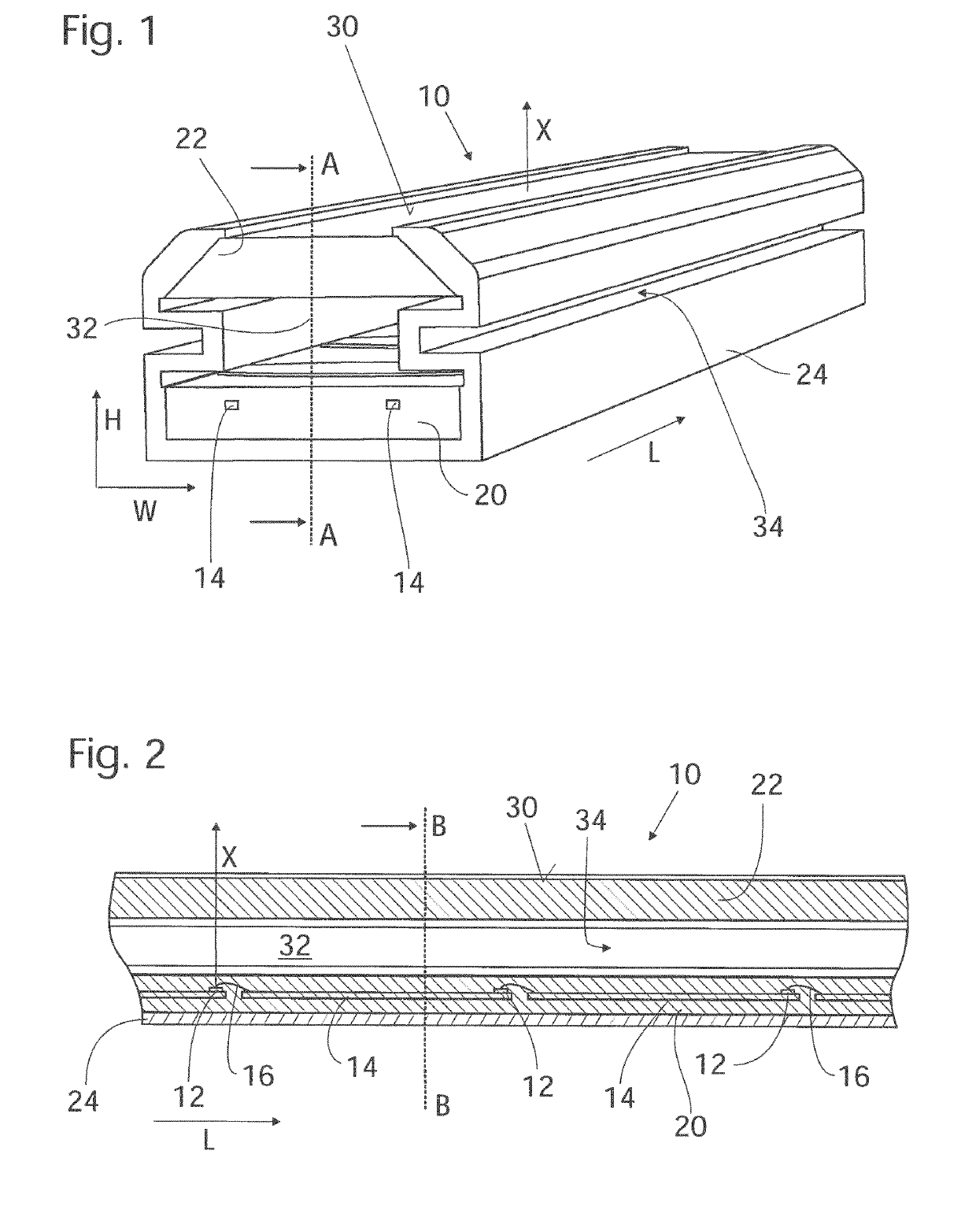
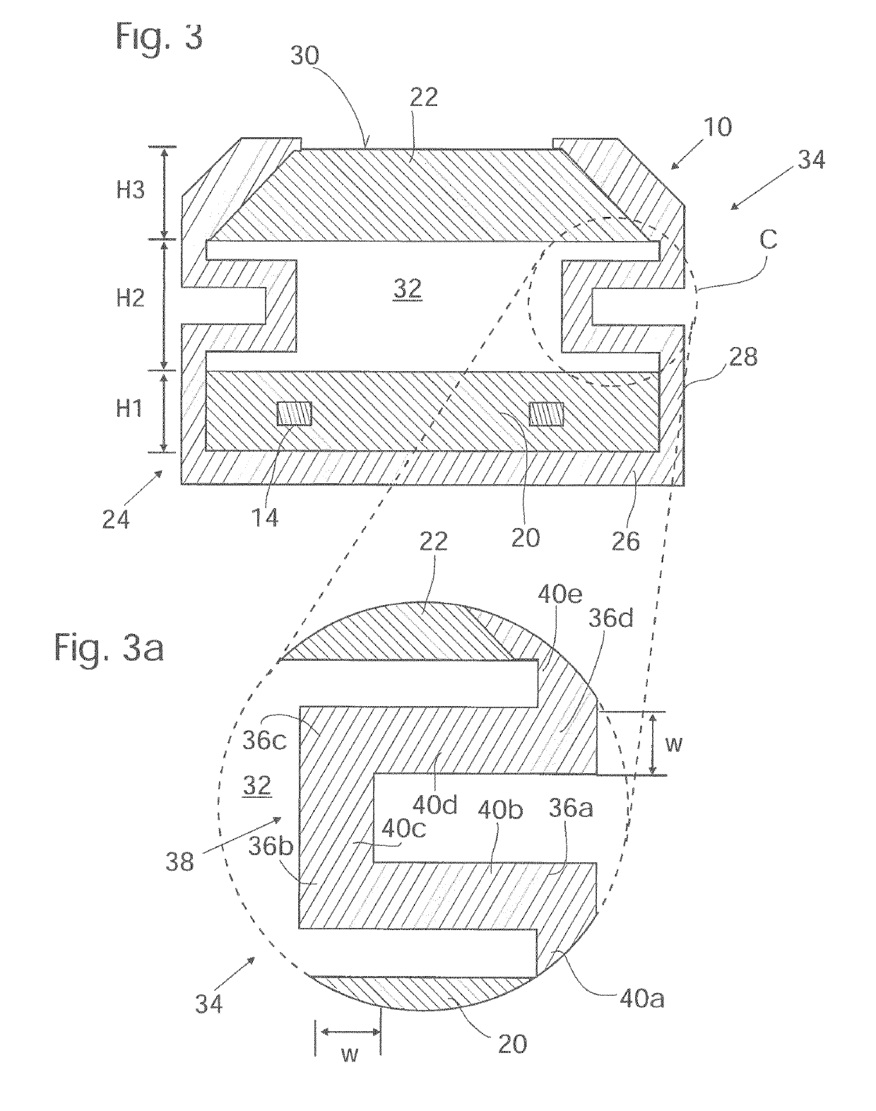
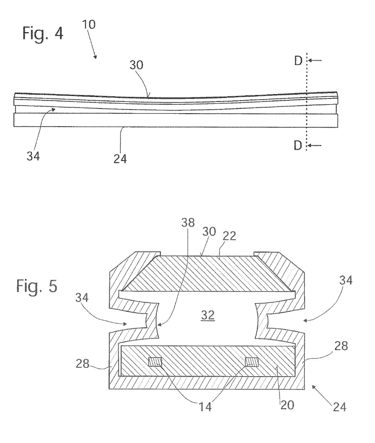
[0036]FIG. 1-3 show a first embodiment of a lighting device 10. The lighting device 10 is of elongate shape with a high aspect ratio, i. e. with a long extension in length direction L as compared to width W and height H.

[0037]The lighting device 10 comprises, as shown in FIG. 2, a plurality of spaced apart LED elements 12 provided as unpackaged LED dies mounted on conductor elements 14 of a lead frame and further contacted by bond wires 16. The LED elements 12 are arranged in a line extending in longitudinal direction L. Their main emission direction X is directed along the height direction H of the lighting device 10.

[0038]The lighting device 10 further comprises a light guide comprised of a first light guide portion 20 and a second light guide portion 22. The light guide and the LED 3o elements 12 mounted on the lead frame 14 are contained within an enclosure 24.

[0039]The light guide portions 20, 22 are solid bodies made of transparent silicone. The enclosure 24 is a hollow body w...


PUM

PropertyMeasurementUnit
aspect ratioaaaaaaaaaa
bending radiusaaaaaaaaaa

Abstract

A lighting device comprises at least one LED element for emitting light into an emission direction. A bendable light guide is arranged to guide light emitted from the LED element. The bendable light guide comprises at least a first portion formed of an elastic, light transmitting light guide material covering at least the emission direction of the LED element, and a second portion formed of an elastic, light transmitting light guide material. In order to be able to function under varying environmental conditions, the second portion is arranged spaced from the first portion in the emission direction by a separation space.

Description

FIELD OF THE INVENTION[0001]The invention relates to a lighting device. More specifically, the invention relates to a lighting device including one or more LED elements and a light guide arranged to guide light emitted from the LED elements.BACKGROUND OF THE INVENTION[0002]Lighting devices comprising LED elements are used for an ever increasing number of lighting applications. A lighting device may comprise a light guide arranged to guide light emitted from an LED element. The light guide may serve different optical functions, e.g. to collimate, diffuse, mix, or direct the emitted light.SUMMARY OF THE INVENTION[0003]It may be considered an object to provide a lighting device with at least one LED element and a light guide, which is operable under changing environmental conditions.[0004]The object may be achieved by a lighting device according to claim 1. Dependent claims relate to preferred embodiments of the invention.[0005]The present inventors have considered lighting devices inc...

Claims


Application Information

Patent Timeline
Patent Type & Authority Applications(United States)
IPC IPC(8): F21S4/22F21V8/00F21V15/01
CPCF21S4/22F21V15/01G02B6/0095F21Y2115/10F21Y2103/10F21V3/062
Inventor MONESTIER, FLORENTKLEIJNEN, CHRISTIAN
Owner LUMILEDS
Why Eureka
Try Eureka