Test cell for evaluating phosphor

a test cell and phosphorescence technology, applied in the field of phosphor testing methods and apparatuses, can solve the problems of virtually impossible life testing, inability to perform plurality of test on a sample, and inability to reliably and accurately measure luminance, so as to eliminate air/dielectric interfaces and improve optical coupling

Inactive Publication Date: 2006-03-02
WORLD PROPERTIES
View PDF41 Cites 2 Cited by
  • Summary
  • Abstract
  • Description
  • Claims
  • Application Information

AI Technical Summary

Benefits of technology

[0015] Another object of the invention is to provide an oil cell that can be operated continuously for long periods in order to provide an indication of the operating life of a phosphor.
[0016] The foregoing objects are achieved in this invention in which an test cell is adapted for both making and testing samples. The cell includes a bottom plate and a top plate having concentric apertures defining a central test cavity. A post attached to the bottom plate closes off the bottom of the test cavity. A slide closes off the top of the test cavity. The top of the post is spaced slightly from the underside of the slide to define a test cavity of substantially uniform thickness. The test cavity is filled with phosphor suspended in uncured resin, closed, and the resin is cured. Once cured, the sample is stable, although delicate, and can be re-measured several times with reproducible results. The measurement takes place in the cell, using a thin film of oil for wetting surfaces to improve optical coupling and to eliminate air / dielectric interfaces.

Problems solved by technology

This mobility is believed to be one of the causes of unstable and non-reproducible measurements of luminance from an oil cell.
The variability means that life testing is virtually impossible because the luminance changes over time for reasons having nothing to do with the life of the phosphor.
The variability also means that performing a plurality of tests on a sample is essentially pointless.
Although phosphor particles in a solid dielectric have less mobility than in a liquid dielectric, the cured layer has a variable thickness across the area thereof, which makes measurements of luminance inconsistent.
The option to date, taking phosphor samples and making complete EL lamps, does not guarantee reproducible results and costs considerable time and money.

Method used


Image

  • Test cell for evaluating phosphor
  • Test cell for evaluating phosphor
  • Test cell for evaluating phosphor

Examples


Embodiment Construction

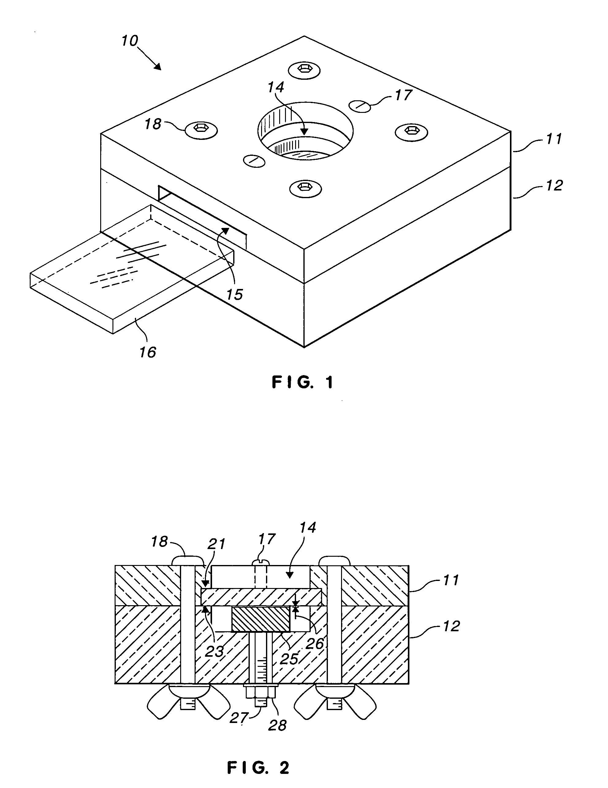
[0022]FIG. 1 is a perspective view of an oil cell constructed in accordance with a preferred embodiment of the invention. Cell 10 includes top plate 11 made from a suitable plastic such as Plexiglass® acrylate (poly(methyl methacrylate)) or Delrin® acetal resin. Bottom plate 12 is preferably made, from Macor® machinable glass ceramic. Other dimensionally stable, rigid materials could be used instead for either plate. The two plates define central cavity 14 wherein samples are made and tests are performed.

[0023] Window 15 is located in one side of top plate 11 and extends to cavity 14. Glass slide 16 fits within window 15 and is inserted into the cell to intersect cavity 14, approximately bisecting the cavity and closing off the upper portion of the cavity. Within cell 10, slide 16 is held in place by set screws, such as set screw 17, which is preferably made from nylon to avoid cracking slide 16. Top plate 11 is fastened to bottom plate 12 by bolts, such as bolt 18.
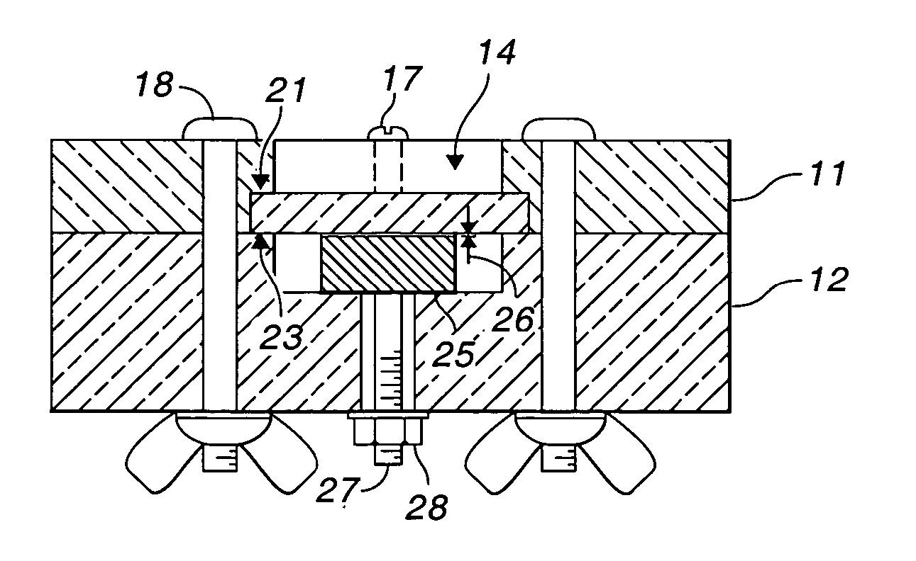
[0024]FIG. 2 is...


PUM

PropertyMeasurementUnit
frequencyaaaaaaaaaa
thicknessaaaaaaaaaa
luminanceaaaaaaaaaa

Abstract

An test cell is adapted for both making and testing samples. The cell includes a bottom plate and a top plate having concentric apertures defining a central test cavity. A post attached to the bottom plate closes off the bottom of the test cavity. A slide closes off the top of the test cavity. The top of the post is spaced slightly from the underside of the slide to define a test cavity of substantially uniform thickness. The test cavity is filled with phosphor suspended in uncured resin, closed, and the resin is cured. Once cured, the sample is stable, although delicate, and can be re-measured several times with reproducible results. The measurement takes place in the cell, using a thin film of oil for wetting surfaces.

Description

BACKGROUND OF THE INVENTION [0001] This invention relates to a method and apparatus for testing phosphor and, in particular, is an improvement on the “oil cell” method used for almost fifty years. [0002] The method and apparatus are described in the context of phosphor for thick film electroluminescent (EL) lamp. Any kind of phosphor can be tested with the new apparatus and method. [0003] An EL lamp is essentially a capacitor having a dielectric layer between two conductive electrodes, one of which is transparent. The dielectric layer can include phosphor particles or there can be a separate layer of phosphor particles adjacent the dielectric layer. The phosphor particles radiate light in the presence of a strong electric field, using relatively little current. [0004] EL phosphor particles are typically zinc sulfide-based materials, including one or more compounds such as copper sulfide (Cu2S), zinc selenide (ZnSe), and cadmium sulfide (CdS) in solid solution within the zinc sulfide...

Claims


Application Information

Patent Timeline
Patent Type & Authority Applications(United States)
IPC IPC(8): G01N21/64
CPCG01N21/643G01N21/03
Inventor BROWER, KAREN RUTHCHANCELLOR, ROY SCOTTCOGHLAN, WILLIAM A.HOOKE, WILL MELVELL JR.KEMPTON, CURTIS HENRYTHOMAS, ALAN C.
Owner WORLD PROPERTIES
Why Eureka
Try Eureka