Heat exchanger and air-conditioner

a technology of heat exchanger and air conditioner, which is applied in the direction of indirect heat exchanger, light and heating apparatus, refrigeration components, etc., can solve the problems of affecting the operation of the heat exchanger, so as to achieve the effect of convenient setting

Inactive Publication Date: 2019-09-12
HITACHI JOHNSON CONTROLS AIR CONDITIONING INC
View PDF0 Cites 1 Cited by
  • Summary
  • Abstract
  • Description
  • Claims
  • Application Information

AI Technical Summary

Benefits of technology

[0006]Note that one factor greatly influencing performance of the heat exchanger is a fin pitch as an interval between adjacent fins. For example, a relatively-shorter fin pitch results in a greater number of fins per unit length (i.e., a larger heat transfer area). As a result, a heat exchange efficiency is increased. However, ventilation resistance is increased on the other hand. This brings an increase in fan power consumption. A relatively-longer fin pitch results in smaller ventilation resistance. However, the number of fins per unit length is decreased on the other hand. This leads to lowering of the heat exchange efficiency. For both of the ventilation resistance and the heat exchange efficiency, it has been demanded that the fin pitch is accurately and easily set.
[0007]For these reasons, the present embodiment is intended to provide a heat exchanger and an air-conditioner configured so that a fin pitch can be accurately and easily set.
[0009]According to the present disclosure, the heat exchanger and the air-conditioner configured so that the fin pitch can be accurately and easily set can be provided.

Problems solved by technology

However, there is a probability that the provided louvers result in a ventilation resistance increase.
In some cases, the condensed water might be frozen and interfere with drainage.
However, microfabrication is necessary, and for this reason, it is difficult to form a shape as designed.
This brings an increase in fan power consumption.
A relatively-longer fin pitch results in smaller ventilation resistance.
This leads to lowering of the heat exchange efficiency.

Method used


Image

  • Heat exchanger and air-conditioner
  • Heat exchanger and air-conditioner
  • Heat exchanger and air-conditioner

Examples


first embodiment

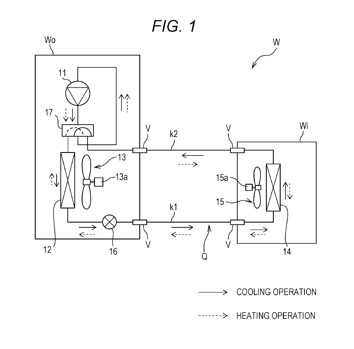
[0022]FIG. 1 is a configuration diagram of a refrigerant circuit Q of an air-conditioner W. Note that solid arrows of FIG. 1 indicate a refrigerant flow in cooling operation. On the other hand, dashed arrows of FIG. 1 indicate a refrigerant flow in heating operation. The air-conditioner W is equipment configured to perform air-conditioning in such a manner that refrigerant circulates in a refrigeration cycle (a heat pump cycle). As illustrated in FIG. 1, the air-conditioner W includes a compressor 11, an outdoor heat exchanger 12 (a heat exchanger), an outdoor fan 13, an indoor heat exchanger 14 (a heat exchanger), an indoor fan 15, a throttle device 16 (an expansion valve), and a four-way valve 17.

[0023]In an example illustrated in FIG. 1, the compressor 11, the outdoor heat exchanger 12, the outdoor fan 13, the throttle device 16, and the four-way valve 17 are provided at an outdoor unit Wo. On the other hand, the indoor heat exchanger 14 and the indoor fan 15 are provided at an i...

second embodiment

[0056]In a second embodiment, the shape of a cutout 31A of a flat pipe 3A (see FIG. 5) is different from the shape of the cutout 31 of the first embodiment. Moreover, the second embodiment is different from the first embodiment in that an opening distance L of an opening 41 (see FIG. 5) is relatively long and each fin collar 41a is pressed against a first inclined surface 31a. Note that other configurations are similar to those of the first embodiment. Thus, the configurations different from those of the first embodiment will be described below. Overlapping configuration description will be omitted.

[0057]FIG. 5 is a partially-enlarged perspective view in a state before each fin collar 41a contacts the cutout 31A, the partially-enlarged perspective view including a longitudinal section of a heat exchanger KA according to the second embodiment. That is, in FIG. 5, fins 4A are not brazed in the middle of assembly with the flat pipe 3A. As in the first embodiment, the multiple linear cu...

third embodiment

[0064]A third embodiment is different from the first embodiment in that each cutout 31B formed at a flat pipe 3B (see FIG. 7) is curved as viewed in a longitudinal section and each fin collar 41Ba is also curved accordingly as viewed in the longitudinal section. Note that other configurations are similar to those of the first embodiment. Thus, the configurations different from those of the first embodiment will be described below. Overlapping configuration description will be omitted.

[0065]FIG. 7 is a partially-enlarged perspective view including a longitudinal section of a heat exchanger KB according to the third embodiment. As illustrated in FIG. 7, the multiple linear cutouts 31B are formed at predetermined intervals each equal to fin pitches P on both of upper and lower sides of the flat pipe 3B in a flat shape as viewed in the longitudinal section.

[0066]Each of the multiple cutouts 31B is in a curved shape as viewed in the longitudinal section. On the other hand, each opening 4...


PUM


Abstract

Provided is a heat exchanger which includes: a flat pipe as a heat transfer pipe in which refrigerant flows; and multiple fins having openings for inserting the flat pipe and arranged at a predetermined interval in a length direction of the flat pipe. At the flat pipe, multiple linear cutouts used for positioning the multiple fins are formed at the predetermined interval in the length direction of the flat pipe, and at least part of an edge of each opening contacts a corresponding one of the cutouts.

Description

CROSS-REFERENCE TO RELATED APPLICATION[0001]This application claims the benefit of priority to Japanese Patent Application No. 2018-044511 filed with the Japan Patent Office on Mar. 12, 2018, the disclosures of all of which are hereby incorporated by reference in their entireties.TECHNICAL FIELD[0002]The present disclosure relates to a heat exchanger and an air-conditioner.BACKGROUND ART[0003]A parallel flow heat exchanger has been known as a heat exchanger used for, e.g., an air-conditioner. The parallel flow heat exchanger is configured to distribute refrigerant to multiple flat pipes through a header and to further cause the refrigerant to join together at another header through each flat pipe. A technique known as an example of the parallel flow heat exchanger is disclosed in Japanese Patent Application Publication No. 2011-043322 A.[0004]That is, Japanese Patent Application Publication No. 2011-043322 A discloses the heat exchanger including multiple tubes having a flat section...

Claims


Application Information

Patent Timeline
Patent Type & Authority Applications(United States)
IPC IPC(8): F28D7/00F28F1/12F28F9/02
CPCF28F9/02F28F1/12F28D7/0066F25B39/00F28F1/30F28D1/05366F28D2021/0068F28F1/022F28F1/325F28F2001/428F28F2275/10F28F2275/14F28F2275/16
Inventor SATO, DAIWASASAKI, SHIGEYUKIMAITA, HIROSHIENDO, TAKESHI
Owner HITACHI JOHNSON CONTROLS AIR CONDITIONING INC
Why Eureka
Try Eureka