Multifunctional system integrator
a multi-functional, system integrator technology, applied in the direction of dc network circuit arrangement, coupling device connection, coupling device details, etc., can solve the problems of network damage, safety risk, difficult and expensive routing of network cables,
- Summary
- Abstract
- Description
- Claims
- Application Information
AI Technical Summary
Benefits of technology
Problems solved by technology
Method used
Image
Examples
third embodiment
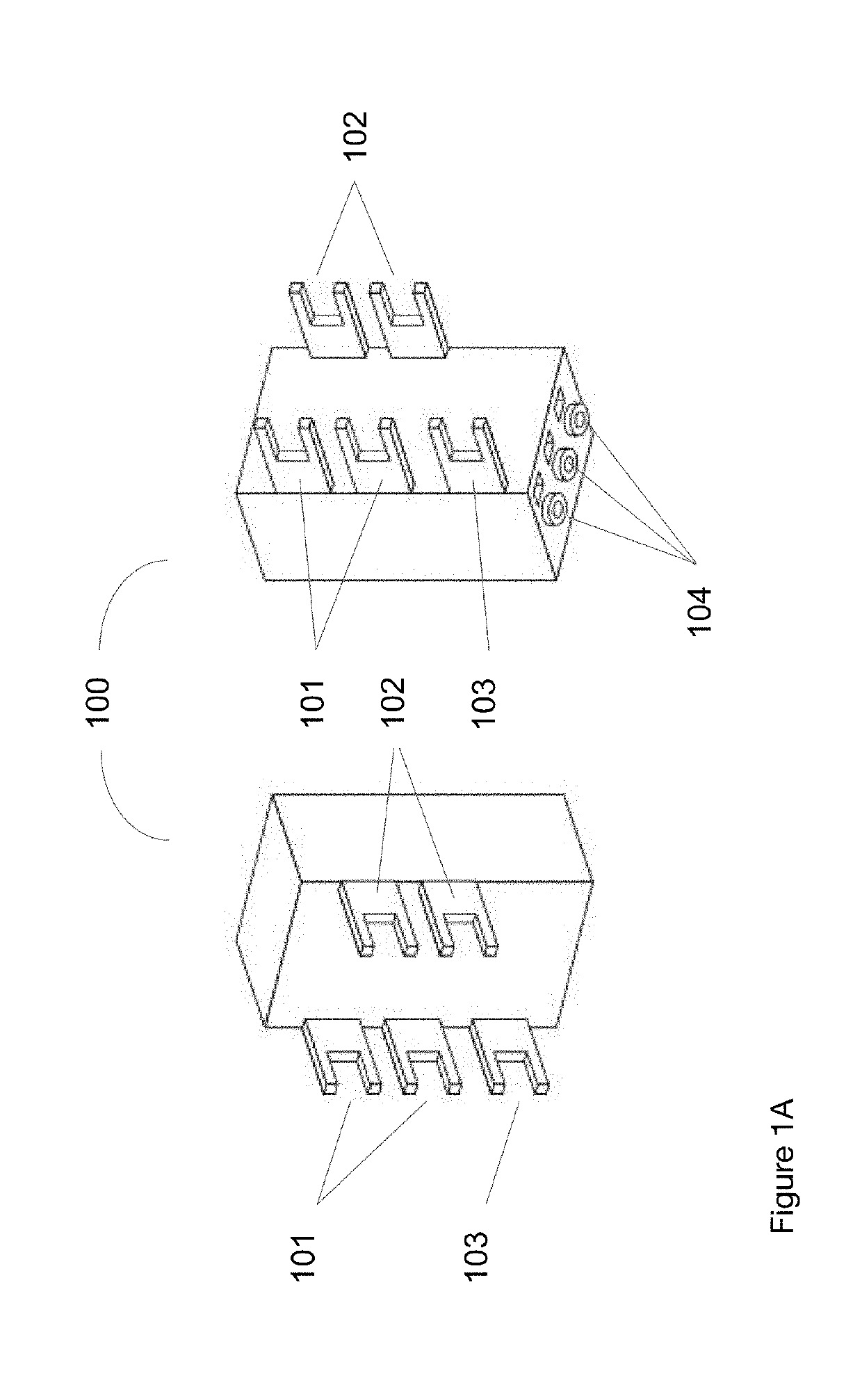
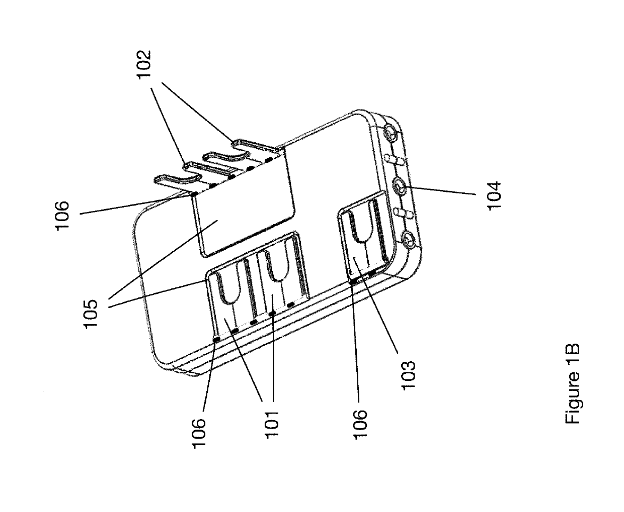
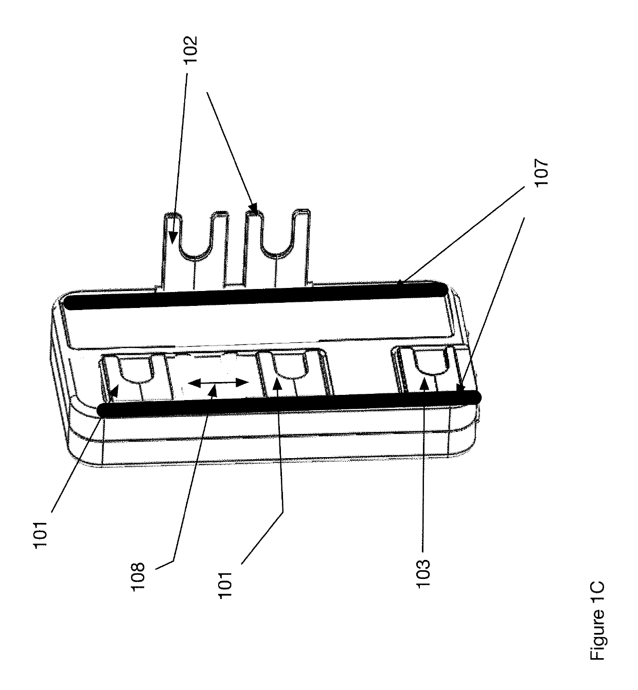
[0043]FIG. 1C shows the multifunctional system integrator of FIG. 1A wherein at least one of the terminals 101, 102, 103 are mounted within slots 107 that enable movement of the terminals 101-103 in the direction 108. In one embodiment the terminals 101-103 are disconnected from the electronics within the multifunctional system integrator 100 when in the lowered position as shown for terminals 101, 103 and connected to the internal electronics when in the raised position as shown for terminals 102. The terminals and the multifunctional system integrator further include a slide and lock mechanism within the slots 107 that enable movement in the direction 108 when in a lowered position as shown for terminals 101, 103 and are locked in place when raised as shown for terminal 102.
[0044]FIG. 2 shows a left side view of a duplex receptacle 200 aligned with the controller module 100. The output terminals for the hot supply line 102 on module 100 are aligned with the input terminals 202 for...
second embodiment
[0050]FIG. 7 shows an assembly 700 including a second embodiment assembly controller module 701 attached to a duplex receptacle 200 and aligned with a standard electrical box 401 and a removable user interface faceplate 702. Module 701 includes a user interface control circuit that attaches to faceplate 702 using flexible ribbon cable 705. The figure shows user interface controls for the Reset 703 and Test 704 functions that are associated with a GFCI capability.
[0051]FIG. 8 shows a typical room 801 in a house that include outlets 802, switches 803 and other electrical devices such as hard wired lighting 804. Each of the devices 802 would include electrical boxes that in the present invention include the electronics described in FIGS. 1-7 and the following Figures. FIG. 9 shows a typical building that includes a plurality of rooms. The floor plan includes a main building 901 and a nearby building 902. Typically, these would represent a house 901 and a garage 902. However, the invent...
PUM
 Abstract
Description
Claims
Application Information
 - R&D
- Intellectual Property
- Life Sciences
- Materials
- Tech Scout
- Unparalleled Data Quality
- Higher Quality Content
- 60% Fewer Hallucinations
Browse by: Latest US Patents, China's latest patents, Technical Efficacy Thesaurus, Application Domain, Technology Topic, Popular Technical Reports.
© 2025 PatSnap. All rights reserved.Legal|Privacy policy|Modern Slavery Act Transparency Statement|Sitemap|About US| Contact US: help@patsnap.com


