In-Vehicle Control Apparatus
a technology for controlling apparatus and vehicles, applied in the direction of diagnostic recording/measuring, instruments, tractors, etc., can solve the problems of delay in the direction of directing the driver to the vicinity of the vehicle, and the driver may become unable to driv
- Summary
- Abstract
- Description
- Claims
- Application Information
AI Technical Summary
Benefits of technology
Problems solved by technology
Method used
Image
Examples
first embodiment
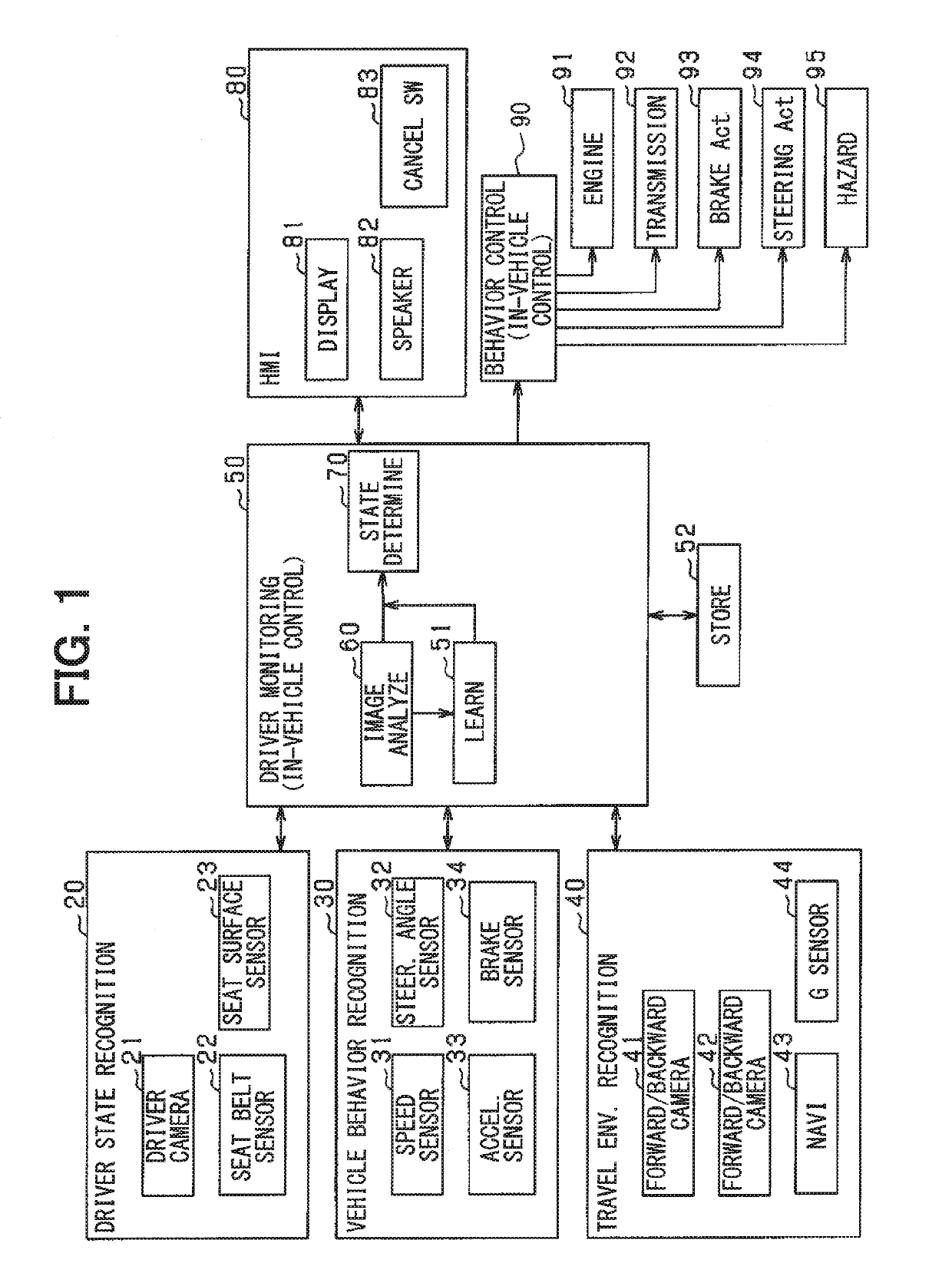
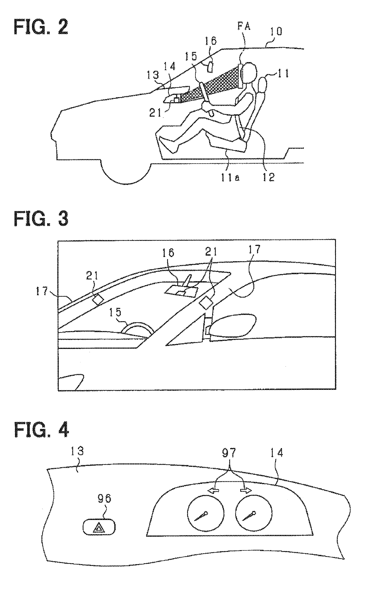
[0021]An embodiment of the present disclosure will be described with reference to the accompanying drawings. The description below explains a configuration of the in-vehicle system according to a first embodiment with reference to FIGS. 1 through 3. The system is mounted on a vehicle and includes an in-vehicle control apparatus, a driver state recognition apparatus 20, a vehicle behavior recognition apparatus 30, a travel environment recognition apparatus 40, and an HMI (Human Machine Interface) 80. The in-vehicle control apparatus includes a driver monitoring apparatus 50 and a behavior control apparatus 90. A vehicle mounted with the system is also referred to as a host vehicle or as a subject vehicle. The driver monitoring apparatus 50 determines whether the driver is under driving inability state where the driver is unable to drive, based on information from the recognition apparatuses, and notifies the HMI 80 and the behavior control apparatus 90 of a possible result of the det...
second embodiment
[0107]A second embodiment issues both a first alarm and a second alarm, which are issued outwardly from the vehicle. The first alarm is issued by using the hazard lamp 95 immediately after the driver is determined to be unable to drive. The second alarm is issued by the hazard lamp 95 following confirming no response from the driver after a lapse of specified time from a point to start the first alarm; the second alarm is issued in a mode more easily recognized around the host vehicle than the first alarm.
[0108]FIG. 8 is a flowchart illustrating a process according to the present embodiment. The driver monitoring apparatus 50 performs this process that replaces the process in FIG. 6. The mutually corresponding parts in FIGS. 8 and 6 are designated by the same reference symbols and a description is omitted for the purpose of illustration. In FIGS. 8, S31 and S32 are newly added.
[0109]At S11 through S14 in FIG. 8, it is determined whether the driver is unable to drive. The processing ...
third embodiment
Other Examples of Third Embodiment
[0122]The following conditions may be satisfied to select the alarm of immediately flashing the hazard lamp 95 or the alarm of confirming the driver's response and then flashing the hazard lamp 95 when the driver is determined to be unable to drive.
[0123]A vehicle speed of the vehicle 10 may be used to select the alarm of immediately flashing the hazard lamp 95 or the alarm of confirming the driver's response and then flashing the hazard lamp 95. Specifically, a vehicle speed threshold value (e.g., a specified speed ranging from 40 to 80 km / h) is predetermined. At S41 and S42 in FIG. 9, it is determined whether a speed at the determination on the driver's inability to drive is higher than or equal to the threshold value. If the vehicle speed is higher than or equal to the threshold value, the driver monitoring apparatus 50 immediately flashes the hazard lamp 95 when the driver is determined to be unable to drive (S15). If the vehicle speed is lower ...
PUM
 Abstract
Description
Claims
Application Information
 - R&D
- Intellectual Property
- Life Sciences
- Materials
- Tech Scout
- Unparalleled Data Quality
- Higher Quality Content
- 60% Fewer Hallucinations
Browse by: Latest US Patents, China's latest patents, Technical Efficacy Thesaurus, Application Domain, Technology Topic, Popular Technical Reports.
© 2025 PatSnap. All rights reserved.Legal|Privacy policy|Modern Slavery Act Transparency Statement|Sitemap|About US| Contact US: help@patsnap.com


