Pyrolysis gasifier comprising automatic ash processor

a gasifier and automatic technology, applied in the direction of horizontal gasifiers, gasifier mechanical details, combustible gas production, etc., can solve the problems of difficult scraping off lumps adhering to the floor door, cumbersome repeating the process several times, and reducing the time required for manually processing ash, reducing and eliminating the risk of burning an operator

Active Publication Date: 2019-09-26
LIM YUNG TAEK +1
View PDF0 Cites 2 Cited by
  • Summary
  • Abstract
  • Description
  • Claims
  • Application Information

AI Technical Summary

Benefits of technology

[0012]According to the embodiments of the present invention, it is possible to automatically process ash without requiring an operator to manually process the ash. This makes it possible to continuously operate the pyrolysis gasifier. Thus, there is an effect that the time required for manually processing the ash is reduced and the process efficiency is enhanced.
[0013]In addition, there is an effect that it is possible to eliminate the risk of burning an operator due to the remaining fire or the like in the ash processing process.

Problems solved by technology

Disposal of various kinds of wastes such as municipal waste, industrial waste and the like is problematic.
In this ash processing process, it is difficult to scrape off the lumps adhering to the floor door due to the crank phenomenon.
It is cumbersome to repeat this process several times.
Due to this cumbersome operation, the time required for processing the ash is prolonged, which hinders the continuous process.
The pyrolysis process is unnecessarily delayed, resulting in process inefficiency.
At this time, fire may remain partially on the bottom door even after the pyrolysis is finished.
In this process, there may be posed a problem that the surroundings are contaminated.
Since the temperature inside the tubular body may be high even after pyrolysis, there is a problem that the operator may be exposed to the risk of burns.

Method used


Image

  • Pyrolysis gasifier comprising automatic ash processor
  • Pyrolysis gasifier comprising automatic ash processor
  • Pyrolysis gasifier comprising automatic ash processor

Examples


Embodiment Construction

[0024]Hereinafter, embodiments of the present invention will be described in detail with reference to the drawings. In the following description of the present invention, a detailed description of well-known configurations or functions will be omitted when it determined that such a description may obscure the subject matter of the present invention.

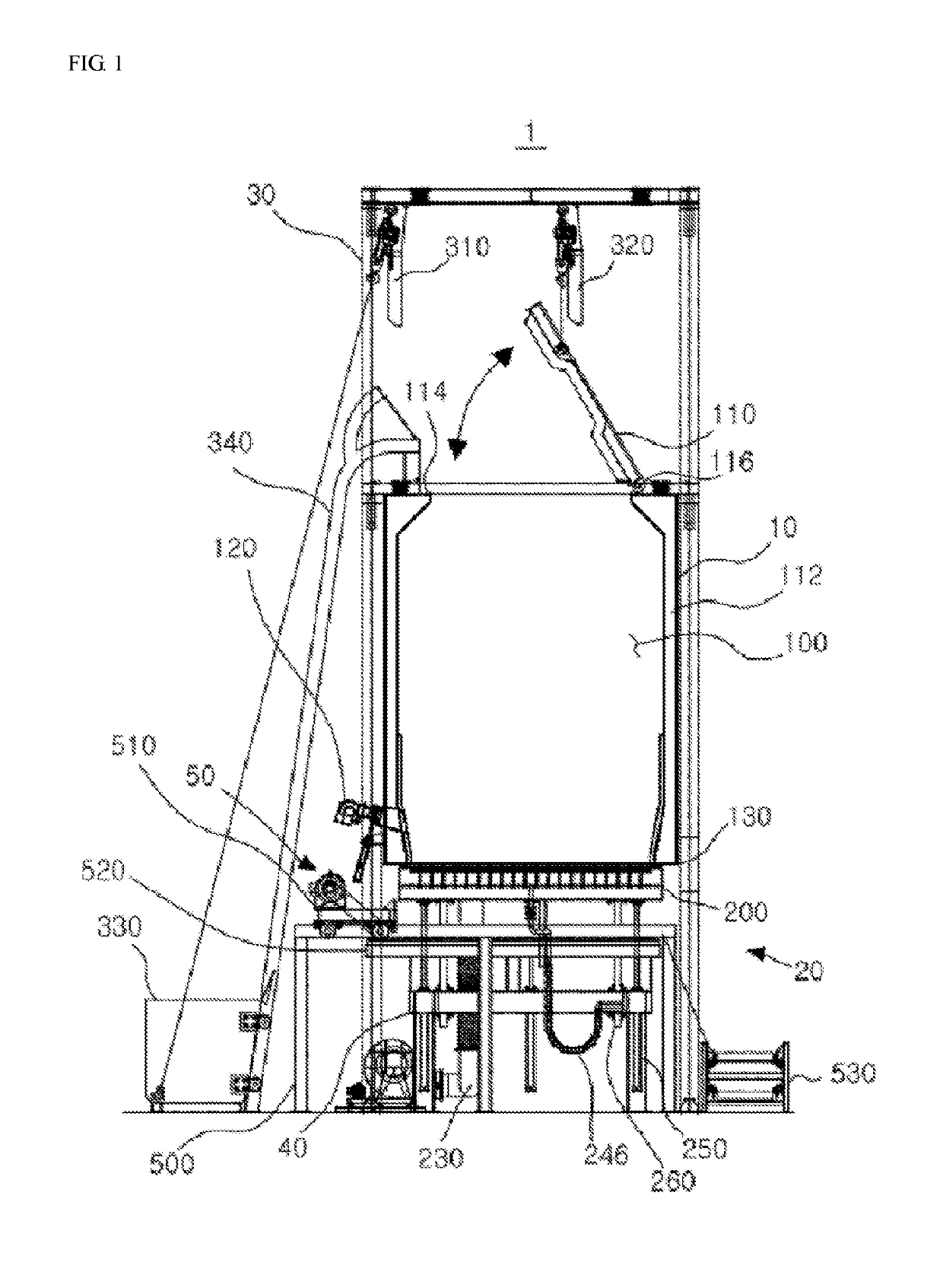
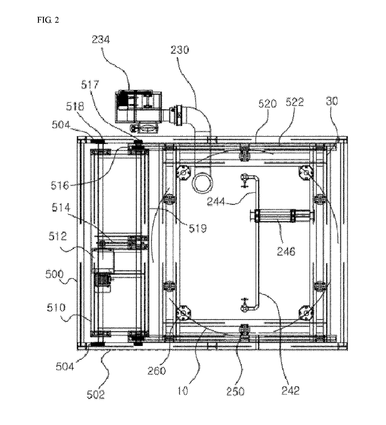
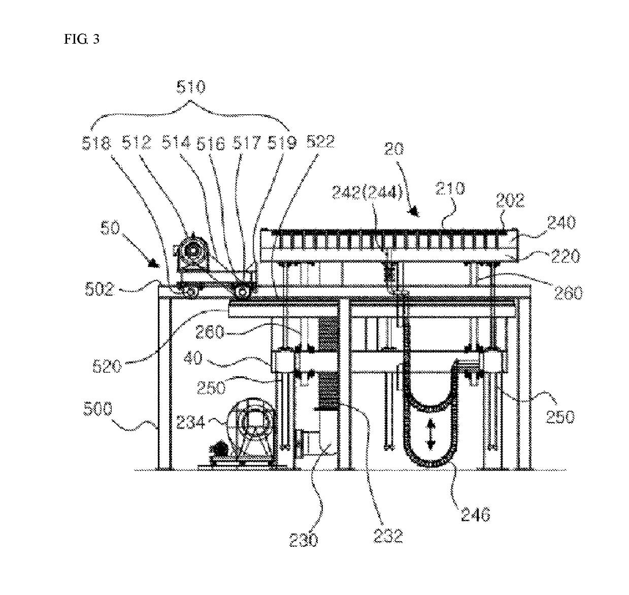
[0025]FIG. 1 is a view showing a pyrolysis gasifier according to an embodiment of the present invention. FIG. 2 is a plan view showing a lower portion of the pyrolysis gasifier shown in FIG. 1. FIG. 3 is an enlarged view showing the lower portion of the pyrolysis gasifier shown in FIG. 1. FIG. 4 is a view of the lower portion of the pyrolysis gasifier shown in FIG. 1, which is seen at an angle different from the angle of FIG. 3.

[0026]Referring to FIGS. 1 to 4, a pyrolysis gasifier 1 according to an embodiment of the present invention may include a tubular body 10 configured to receive and pyrolyze combustible wastes, a bottom door 20 disp...


PUM

PropertyMeasurementUnit
thicknessaaaaaaaaaa
rotational forceaaaaaaaaaa
heightaaaaaaaaaa

Abstract

A pyrolysis gasifier includes a tubular body configured to receive and pyrolyze a combustible waste, a bottom door disposed below the tubular body to selectively seal the tubular body, a main frame supporting the tubular body, a base frame supporting the bottom door, an automatic ash processor configured to, while traveling in one direction, push and remove ash remaining on the bottom door after pyrolysis of the combustible waste, and a guide frame supporting the automatic ash processor and configured to guide the travel of the automatic ash processor.

Description

TECHNICAL FIELD[0001]The present invention relates to a pyrolysis gasifier comprising an automatic ash processor.BACKGROUND ART[0002]Disposal of various kinds of wastes such as municipal waste, industrial waste and the like is problematic. One of the disposal methods of wastes is a method of classifying combustible wastes such as wastes including organic substances that can be used as biomass fuel, polypropylene-based synthetic resins, and the like, pyrolyzing the classified wastes, and driving a turbine or generating a steam by utilizing a combustible gas generated through pyrolysis. Use of the gas generated by pyrolyzing the combustible wastes in the gasifier as described above makes it possible to reduce the emission of a carbon dioxide gas, thereby alleviating the problem of global warming.[0003]A pyrolysis gasifier for pyrolyzing wastes has a principle that local combustion is performed by injecting an air into a bottom door where an air nozzle is embedded to face upward and th...

Claims


Application Information

Patent Timeline
Patent Type & Authority Applications(United States)
IPC IPC(8): C10J3/84
CPCC10J3/84C10J2300/0946C10J2300/1628C10J2200/36C10J3/002C10J3/74C10J2200/09
Inventor LIM, YUNG TAEKRIM, DEOK JUN
Owner LIM YUNG TAEK
Why Eureka
Try Eureka