
Process for manufacturing a hybrid timepiece component

a technology of hybrid timepieces and components, applied in the field of hybrid timepiece components manufacturing, can solve the problems of ensuring the cohesion of the assembly, unable to meet the requirements of mechanical strength, and the timepiece components obtained exhibit a risk of cohesive failure between the two materials, so as to achieve satisfactory mechanical strength and cohesion. the effect of a hybrid timepiece componen

Inactive Publication Date: 2019-09-26
ROLEX SA
View PDF6 Cites 1 Cited by
  • Summary
  • Abstract
  • Description
  • Claims
  • Application Information

AI Technical Summary

Benefits of technology

This approach achieves strong mechanical cohesion and simplifies the manufacturing process by ensuring a single-piece metal structure that securely frames the silicon part, enhancing the component's mechanical strength and stability.

Problems solved by technology

However, this bond is neither a chemical bond nor mechanically strong, since it is only based on the roughness alone of these sides, which may prove too weak to ensure the cohesion of the assembly when it is subjected to certain stresses or to a large temperature variation.
Thus, the timepiece components thus obtained exhibit a risk of cohesive failure between the two materials, that is to say at the bond between the metal and silicon.
However, it requires the use of a complex manufacturing process, in particular due to the obligation to turn over the substrate in order to carry out the growth on the lower surface of the silicon part.
In addition, a weakness is furthermore observed at the interface between the various separate layers of metal formed by the two separate steps of growth of the metal part.

Method used


Image

  • Process for manufacturing a hybrid timepiece component
  • Process for manufacturing a hybrid timepiece component
  • Process for manufacturing a hybrid timepiece component

Examples


Embodiment Construction

[0019]For the sake of simplification, the term “metal” will be used in the following description to denote a metallic material or a metal alloy. Furthermore, the same references will be used for identical or similar elements in the various embodiment variants of the invention.

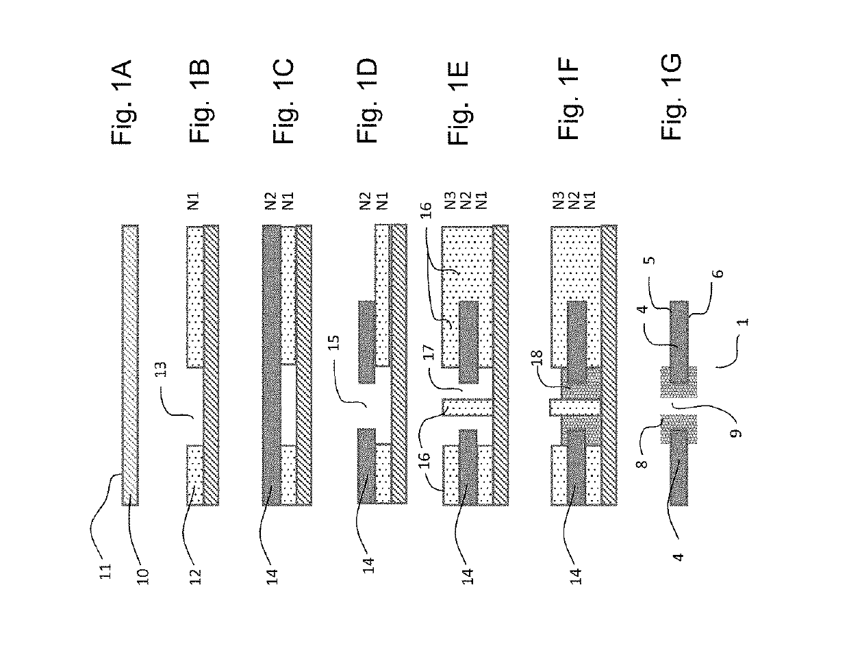
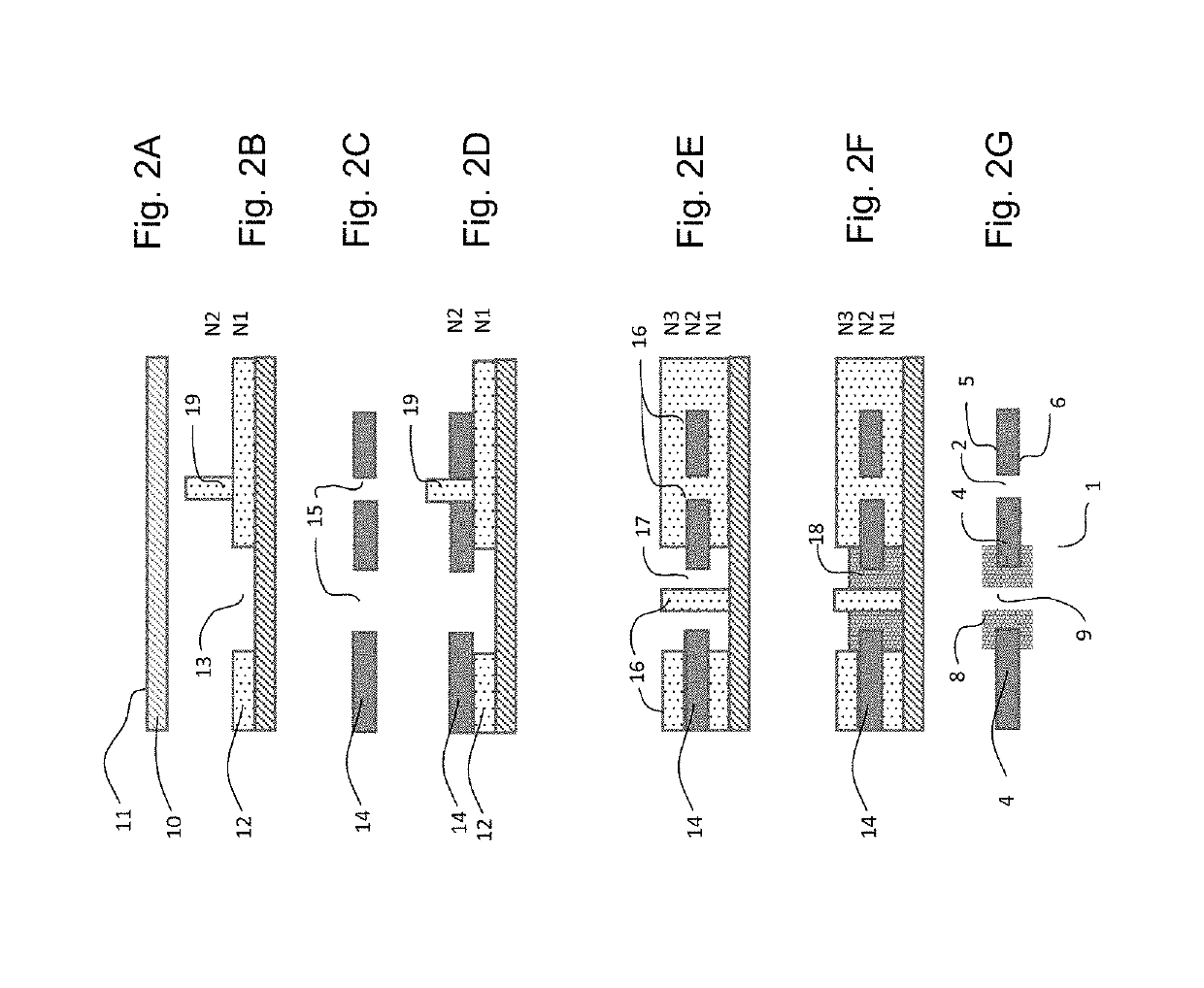
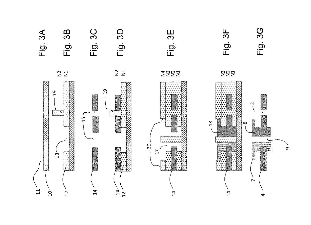
[0020]FIG. 1a illustrates a first step of the process for manufacturing a hybrid timepiece component according to the embodiment of the invention. This step consists in being provided with a working substrate 10 that will act as support for the fabrication of the timepiece component. This substrate is intended to be removed, that is to say that it is not part of the final timepiece component. It is either made of metal or made of any conductive material, or formed using a nonconductive material, the upper surface 11 of which is rendered conductive by metallization. Thus, the working substrate may consist of a silicon wafer comprising a metal layer obtained by PVD deposition or by electroforming, or of a doped s...


PUM

PropertyMeasurementUnit
roughnessaaaaaaaaaa
temperatureaaaaaaaaaa
depositionaaaaaaaaaa

Abstract

Process for manufacturing a hybrid timepiece component, comprising structuring at least one wafer (14) of a first micromachinable material so as to form at least one through-opening (15) within the wafer (14), said structured wafer (14) being intended to form a first part (4) of the hybrid timepiece component; and depositing a metal by electroforming, so that the metal extends through the through-opening (15) and over the two upper and lower faces of the wafer (14) as a single piece resulting from one and the same electroforming step, the electroformed metal being intended to form a second part (8) of the hybrid timepiece component.

Description

[0001]This application is a divisional of U.S. application Ser. No. 15 / 417,854 filed Jan. 27, 2017, each of which claims priority of European patent application No. EP16154126.3 filed Feb. 3, 2016, the content of each of which is hereby incorporated by reference herein in its entirety.BACKGROUND ART[0002]The present invention relates to a process for manufacturing a hybrid timepiece component, comprising at least two different materials. It also relates to a timepiece component as such obtained according to this process, a timepiece movement and a timepiece comprising such a hybrid timepiece component.[0003]It is known to manufacture hybrid timepiece components composed, for example, of a first part made of silicon, or more generally made of any micromachinable material, and of a second part made of metal. One process for manufacturing such a hybrid timepiece component uses a first process for manufacturing by micromachining, in particular by deep reactive-ion etching (DRIE), in ord...

Claims


Application Information

Patent Timeline
Patent Type & Authority Applications(United States)
IPC IPC(8): G04B31/06G04B19/04G04B18/08G04B17/06G04B1/14G04B15/14B81C99/00G04B13/02
CPCG04B19/042G04B18/08G04B31/06G04B15/14B81B2201/035B81C2201/034G04B1/145G04B17/066G04B19/044G04B13/02G04B17/063B81C99/0085G04D3/0069
Inventor BOSSART, RICHARDCALAME, FLORIAN
Owner ROLEX SA
Learn More