
Method for fabrication of a composite part

a composite component and manufacturing method technology, applied in the field of composite component fabrication, can solve the problem that the components obtained by the compacting process always have such cohesion defects, and achieve the effect of fewer implementation steps

Active Publication Date: 2019-05-16
THE SWATCH GRP RES & DEVELONMENT LTD
View PDF1 Cites 0 Cited by
  • Summary
  • Abstract
  • Description
  • Claims
  • Application Information

AI Technical Summary

Benefits of technology

The present invention proposes an alternative method for fabricating a metal-ceramic composite component that requires fewer implementation steps. The method allows for the components to be made mostly of metal or ceramic, and the steps are simpler to implement. The blank formed of the two materials is sintered in a single step and not consecutively for each material, which avoids repeated handling of intermediate components. Despite the significant difference in coefficient of thermal expansion between steel and zirconia, a complex 3D bi-injected component with satisfactory cohesion between its steel and zirconia parts can be obtained using the bi-injection molding method described above. The final finishing step improves the aesthetics of the composite component formed in the previous step.

Problems solved by technology

Despite the similar densities of the two powders, which is a necessary condition to obtain a component having the fewest possible cohesion defects between the two materials after co-sintering, such as cracks, it is noted that according to this publication, components obtained by the compacting process always have such cohesion defects.

Method used


Image

  • Method for fabrication of a composite part

Examples


Embodiment Construction

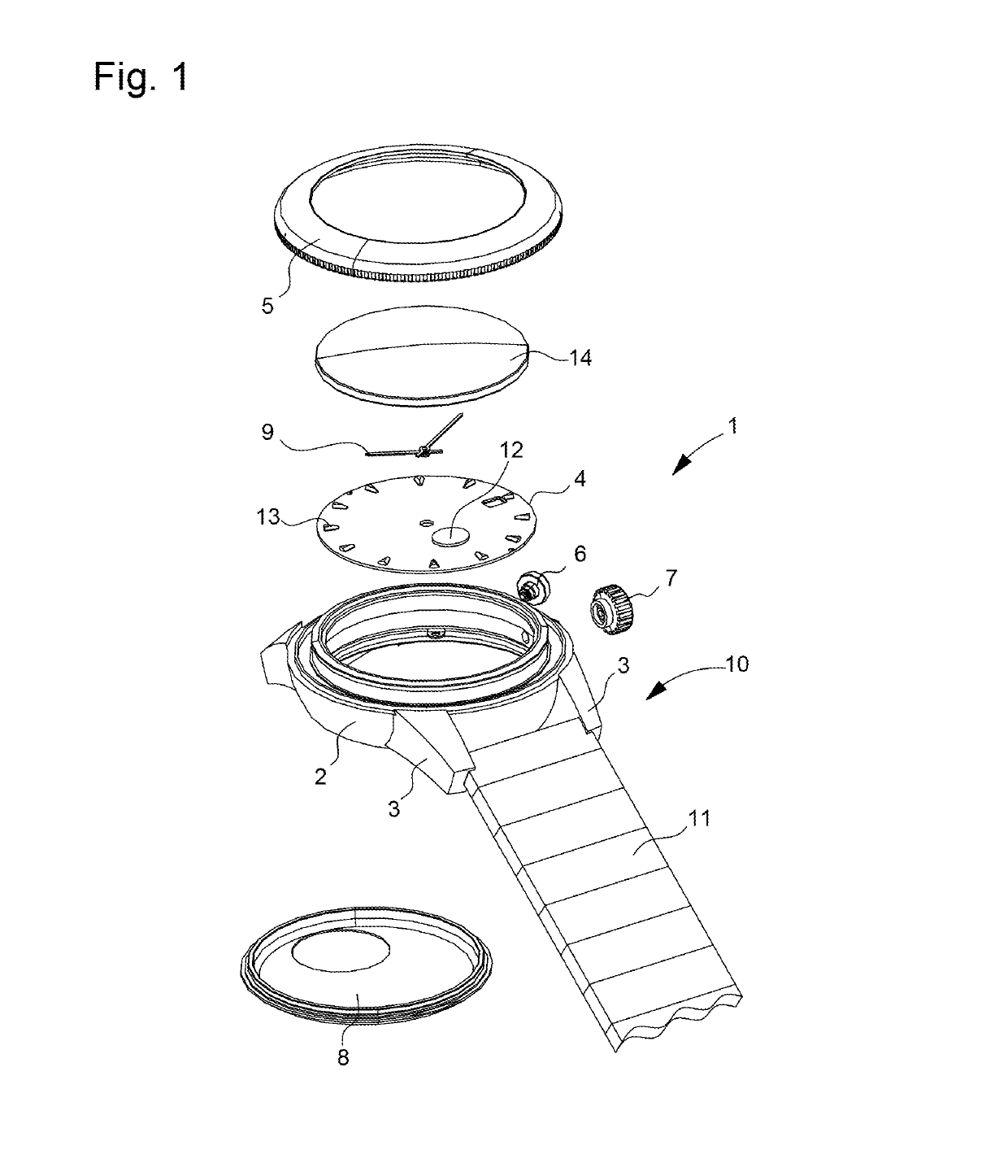
[0028]As explained above, the invention relates to a metal-ceramic composite component. This composite component was devised for applications in the field of horology, such as for example, the external parts of a timepiece. Naturally, the composite component according to the invention is not limited to the external parts of a timepiece and more generally to horology. Thus, in a non-limiting manner, it is also possible to envisage that this composite component could be applied in the field of tableware, cutlery or jewellery.

[0029]By way of non-limiting example and with reference to FIG. 1, the composite component can form, in particular, all or part of a case 1, such as the case middle 2 and horns 3, a dial 4, a flange, a bezel 5, a push-piece 6, a crown 7, a case back cover 8, a hand 9, a bracelet or strap 10 such as a link 11, a decoration 12, an applique 13, a crystal 14 or a clasp.

[0030]The invention also relates to a method for fabrication of a composite component. The method in...


PUM

PropertyMeasurementUnit
Volumeaaaaaaaaaa
Shrinkageaaaaaaaaaa

Abstract

A method for fabrication of a composite component including a first material containing steel 316L and a second material containing zirconia powder formed in a single sintering.

Description

FIELD OF THE INVENTION[0001]The invention relates to a method for fabrication of a composite component and more specifically, a metal-ceramic composite component, i.e. a component combining two distinct materials, respectively made from metal and ceramic.BACKGROUND OF THE INVENTION[0002]EP Patent No EP2380864 discloses the fabrication of a ceramic element inlaid with galvanic decorations. This method provides numerous advantages but requires many implementation steps to be carried out.[0003]The publication entitled ‘Powder compaction of bimaterials: stainless steel 316L and nanocrystalline yttria stabilised zirconia’ describes the forming of a steel 316L and nanocrystalline yttria stabilised zirconia composite by powder compaction or uniaxial pressing. According to this document, a polyvinyl alcohol, in a proportion of 4% by weight, is added to the mixture of each powder as binder. In this forming method of simultaneously pressing two materials, identical densities are obtained for ...

Claims


Application Information

Patent Timeline
IPC IPC(8): B22F7/06B22F3/22B28B1/24B22F3/24B28B11/08A44C5/00
CPCB22F7/06B22F3/225B28B1/24B22F3/24B28B11/0845A44C5/0053B22F2301/35B22F2302/25B22F2003/247G04B19/12G04B19/18G04B3/04G04B37/22G04B39/004G04B19/042C22C33/0285B22F2998/10Y02P10/25B22F3/10B22F3/22B22F3/02B22F10/10B22F10/66
Inventor LUEBBE, HENNINGBOURBAN, STEWES
Owner THE SWATCH GRP RES & DEVELONMENT LTD
Learn More