Caulking gun

a caulking gun and caulking technology, applied in the direction of liquid surface applicators, coatings, etc., can solve the problems of inconvenient use, rise in pressure inside the caulking cartridge, and difference formed between the inside of the caulking cartridge and the adhesive outlet, so as to improve the adaptability of the construction operation, facilitate manufacture and adjustment, and improve the effect of adaptability

Active Publication Date: 2019-10-03
ZHEJIANG VOLCANO MACHINERY
View PDF0 Cites 7 Cited by
  • Summary
  • Abstract
  • Description
  • Claims
  • Application Information

AI Technical Summary

Benefits of technology

[0006]In order to overcome the deficiencies of the prior art, the present invention proposes an innovative caulking gun, which has the effect of ‘one gun for multi-purpose’ to meet the construction requirements of different kinds of adhesives, and is convenient to manufacture and adjust, and is easy to realize the adjustment of the amount of gel breaking, to meet the needs of different applications of the caulking gun, so as to achieve the purpose of improving the adaptability of its construction operation, reducing adhesive waste and saving social resources.

Problems solved by technology

However, the propulsion ratio of the common caulking guns currently on the market is fixed, so that one caulking gun can not meet the construction requirements of different types of adhesives at the same time, therefore, it is necessary to equip multiple caulking guns at the same time in case of need.
However, since the diameter of the output of the adhesive cartridge is smaller than the diameter of the piston inside the adhesive cartridge, in the impelling operation of a conventional caulking gun, the pressure inside the adhesive cartridge will rise, and a pressure difference is formed between the adhesive outlet and the inside of the adhesive cartridge.
If the pressing operation is stopped at this time, the adhesive inside the adhesive cartridge will continue to overflow from the adhesive output under the action of pressure until the pressures inside and outside the adhesive cartridge are equal, what's more, the adhesive push rod of the conventional caulking gun can only advance in one direction and adhesive breaking can only be operated manually, which can only meet the requirements under a single construction condition, and in most cases, it will not only cause inconvenience in use, but also lead to a large waste of adhesive material.

Method used


Image

  • Caulking gun
  • Caulking gun
  • Caulking gun

Examples


embodiment 1

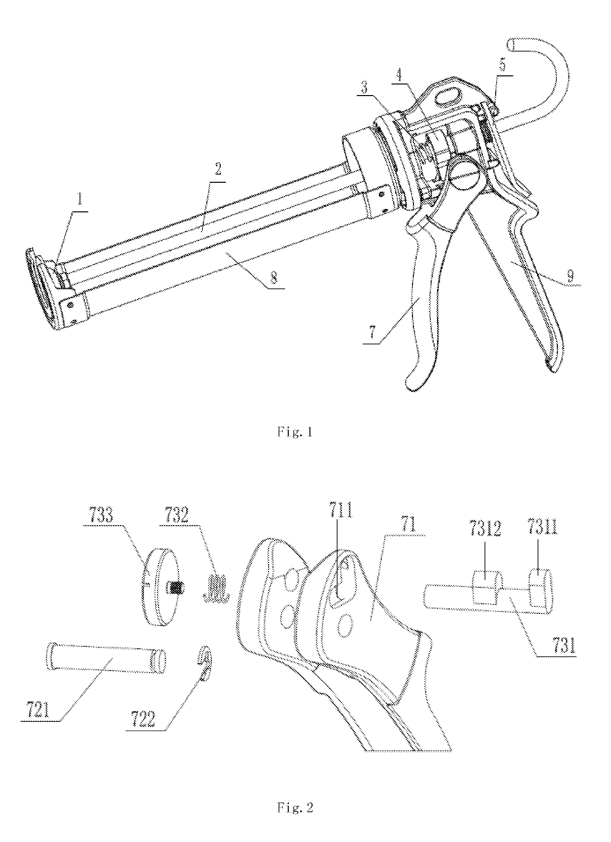
[0036]Referring to FIG. 1 and FIG. 2, Embodiment 1 provides a caulking gun including a pin position switching device, including a push disk 1, a push rod 2, an adhesive cartridge compartment 8, a trigger 7 and a gun body 9. The trigger 7 is hinged to the middle of the gun body 9 by the pin 721 to cooperate with the lower part of the gun body 9 for rubberizing. The adhesive cartridge compartment 8 is disposed at the front end of the gun body 9. The rear end of the push rod 2 is located outside the gun body 9, and the front end of the push rod 2 passes through the gun body 9 and locates in the adhesive cartridge compartment 8, the push disk 1 is disposed at the front end of the push rod 2, the rear end of the push rod 2 is provided with a braking device, and the gun body 9 is mounted with a push piece 4 for driving the push rod 2 to advance. The push piece 4 is provided with a return spring 3 at the front end of the push piece 4; the trigger 7 is provided with a pin position switching...

embodiment 2

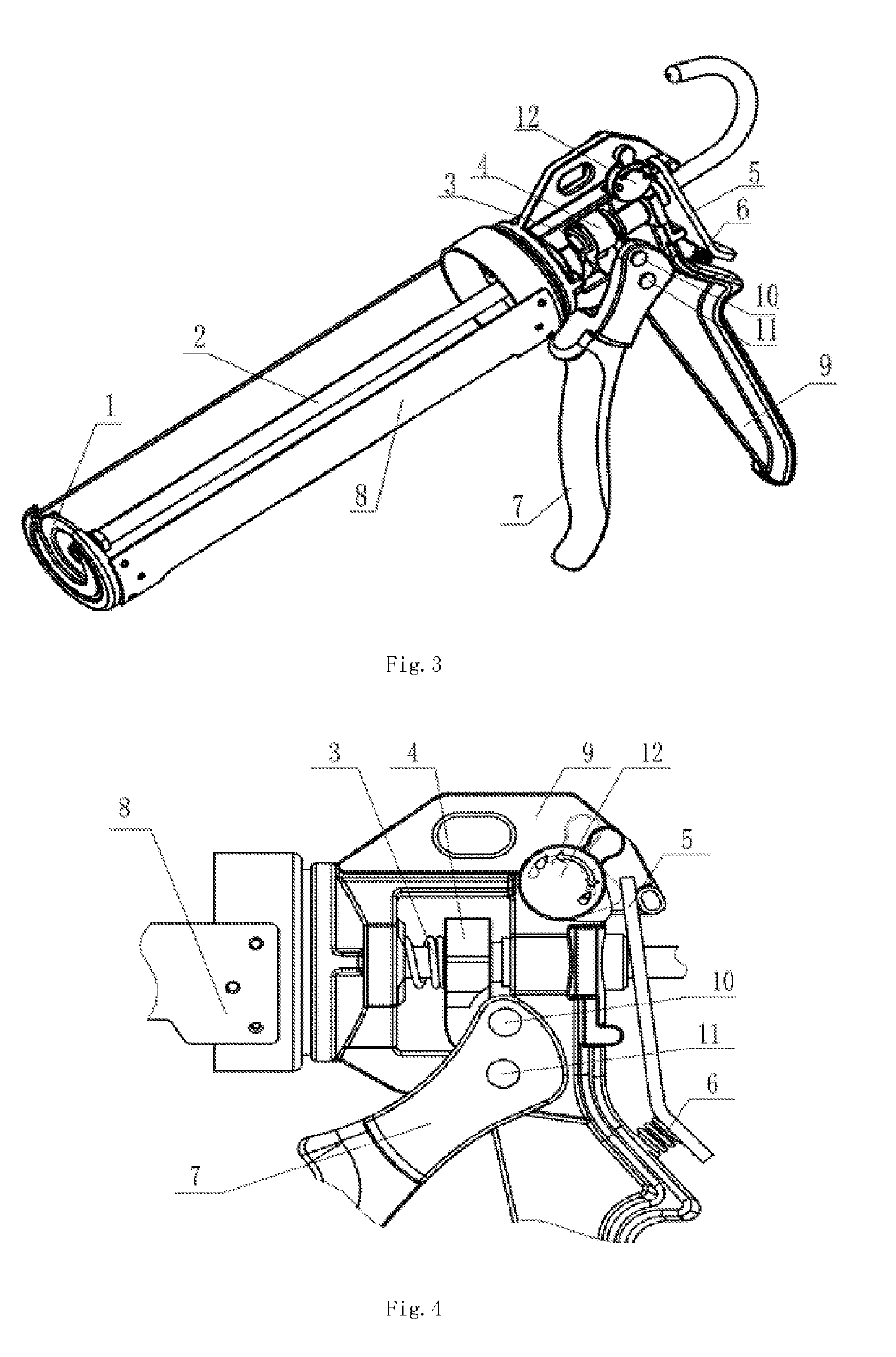
[0041]As shown in FIG. 3, Embodiment 2 provides a caulking gun equipped with a cartridge pressure release switching device, which comprises a push disk 1, a push rod 2, an adhesive cartridge compartment 8, a trigger 7 and a gun body 9. The upper part of the gun body 9 is a frame structure, and a through hole for the push rod 2 to pass through is provided in a horizontal direction; a push piece 4 for driving the push rod 2 to advance is mounted in the frame of the gun body 9. A reset spring 3 is provided at the front end of the push piece 4. A brake plate 5 is disposed outside the frame of the gun body 9 and at the rear end of the push rod, and a brake compression spring 6 is disposed between the gun body 9 and the brake plate 5. The middle portion of the gun body 9 is provided with a through hole perpendicular to the frame body, so that the trigger 7 and the gun body 9 are pin-connected, and cooperate with the handle of the lower half of the gun body 9 to realize the adhesive pressi...

embodiment 3

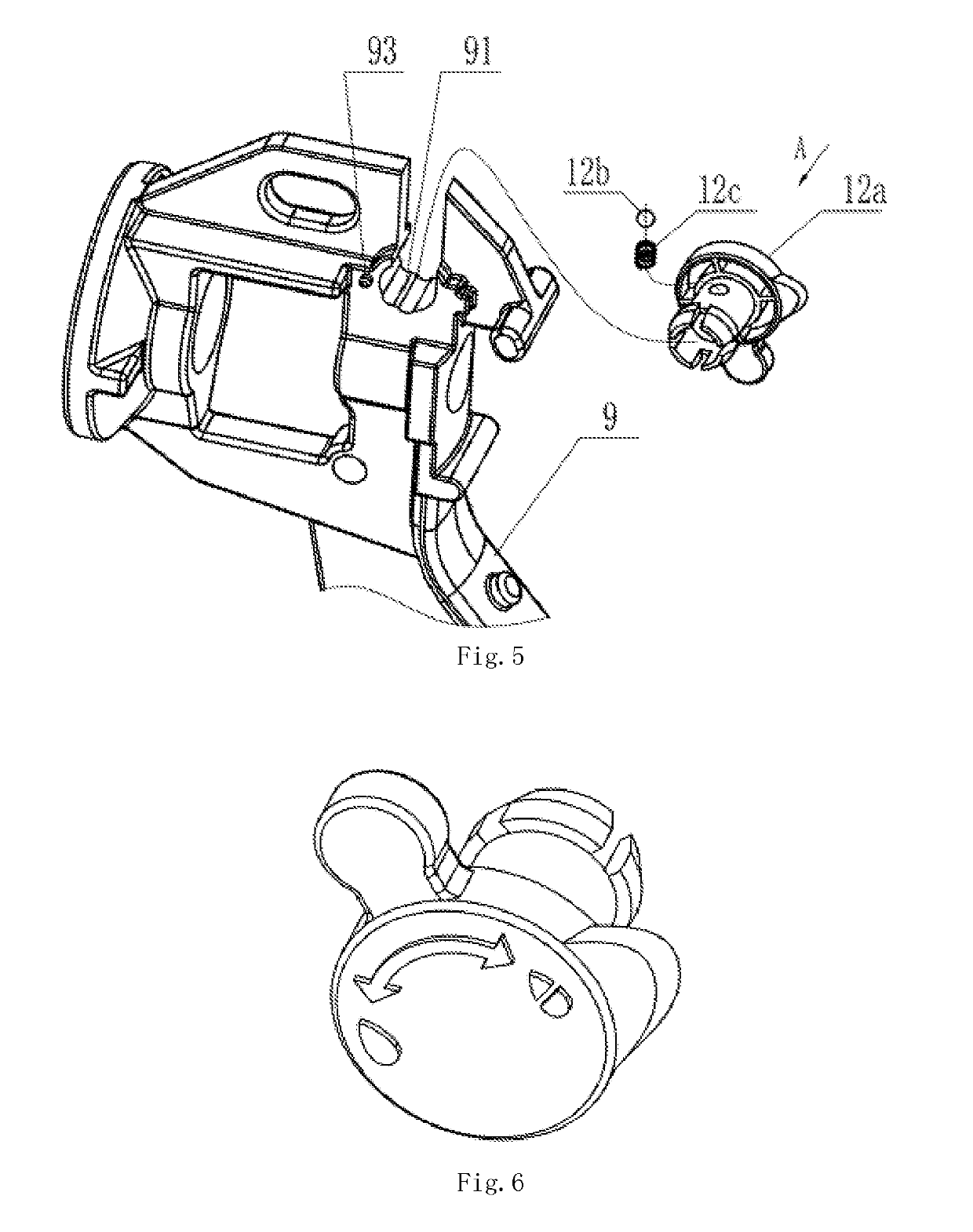
[0048]Referring to FIG. 7 to FIG. 8 , the difference between Embodiment 3 and Embodiment 2 is that a positioning hole 91a and a limiting hole 92 for accommodating the resilient device are respectively disposed on the upper rear side of the gun body 9. The rotary switch includes a left rotary portion 12a1 and a right rotary portion 12a2 that pass through the locating hole 91 on the upper rear side of the gun body 9 face by face and are attached to the gun body 9 by screw 12a3. The resilient device is located in the limiting hole 92 and is compressingly mounted between the gun body and the rotary switch 12a by the inner end surface of the cam portion of the rotary switch 12a.

[0049]The left rotary portion 12a1 has a stepped shaft shape, and one end is provided with a cam portion, the outer ring of the cam portion is respectively provided with a dial portion and a square lug boss, the inner ring of the cam portion is provided with two convex blocks, and the inner end surface is provide...


PUM


Abstract

A caulking gun includes a push disk, a push rod, an adhesive cartridge compartment, a trigger and a gun body; the trigger is hingedly coupled to the middle part of the gun body; the rear end of the push rod is outside the gun body and provided with a braking device; the front end is in the adhesive cartridge compartment through the gun body and provided with a push disk; a push piece for driving the push rod is mounted in the gun body; the front end of the push piece is provided with a return spring; the trigger is provided with a pin position switching device for adjusting the propulsion ratio by adjusting the contact position of the push piece; adjustment of different propulsion ratios enables the caulking gun to be multifunctional to meet the construction requirements of different adhesives.

Description

CROSS-REFERENCE TO RELATED APPLICATION[0001]The present application relies on, for priority, China Patent Application No. 201810579740.3 entitled “caulking gun with a cartridge pressure release switching device”, filed on Jun. 7, 2018, and China Patent Application No. 201810643912.9 entitled “caulking gun with a pin position switching device”, filed on Jun. 21, 2018. The subject matter of each is incorporated by reference herewith in entirety.BACKGROUND OF THE INVENTIONTechnical Field[0002]This invention relates to caulking guns.Description of Related Art[0003]A caulking gun is usually a mechanical squeezing tool that uses the principle of lever to rubberizing. When used in combination with an adhesive cartridge or adhesive stick, the adhesive can be easily pressed out from the front end of the adhesive cartridge to improve the rubberizing efficiency. Therefore, the caulking gun is widely used in the fields of architectural decoration, automobile industry, hardware tools and the lik...

Claims


Application Information

Patent Timeline
Patent Type & Authority Applications(United States)
IPC IPC(8): B05C17/005B05C17/01
CPCB05C17/00593B05C17/01B05C17/0052B05C17/00596B05C17/0123
Inventor XIA, LEZHANG, SUHUASHEN, WEIDONG
Owner ZHEJIANG VOLCANO MACHINERY
Why Eureka
Try Eureka