Cable machine

Active Publication Date: 2019-10-03
CONSTR MECANICAS CABALLE
View PDF17 Cites 1 Cited by
  • Summary
  • Abstract
  • Description
  • Claims
  • Application Information

AI Technical Summary

Benefits of technology

[0009]An object of the invention is to disclose attachment means inside the tube of a rotary winch for a machine for manufacturing cables which ov

Problems solved by technology

Various challenges arise when arranging power elements, for example a reducer, in the space inside the

Method used


Image

  • Cable machine

Examples


Example

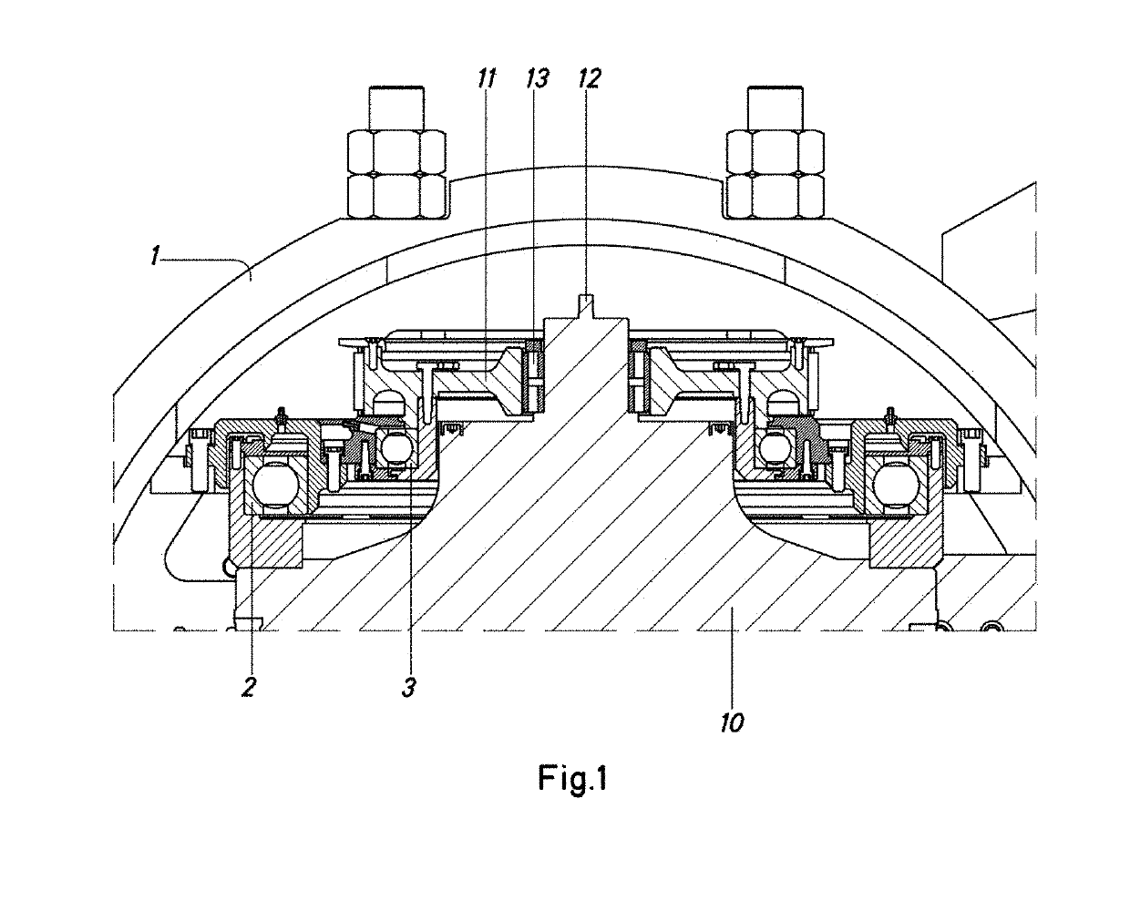
[0021]The FIGURE shows the upper portion of an upper section of the tube -1- of a winch according to the present invention.

[0022]In said FIGURE, two bearings -2-, -3- are shown which are mutually concentric. In particular, both bearings are ball bearings. The outer bearing -2- is attached, by the outer face thereof, to the reducer -10- and, by the inner face thereof, to the inner face of the tube -1-.

[0023]In turn, the inner bearing -3- is attached to the pulley -11- by the inner face thereof and to the outer bearing -2- by the outer face of the inner bearing -3-. In particular, in the example, the inner bearing is attached to the structure that attaches the outer bearing -2- to the tube -1-. According to another aspect, the inner bearing -3- is attached to the inner face of the outer bearing -2-.

[0024]As shown, both bearings -2-, -3- are in different planes. More specifically, the inner bearing -3- is raised with respect to the outer bearing -2-.

[0025]As shown, the pulley -11- is h...


PUM

PropertyMeasurementUnit
Angular velocityaaaaaaaaaa
Speedaaaaaaaaaa

Abstract

A machine for manufacturing cables includes a winch that includes a tube, which includes at least a pulley, a reducer and an input shaft to the reducer in its interior. A system for attaching the reducer includes two concentric bearings. An outer bearing is attached to the reducer and the tube, and an inner bearing is attached to the pulley and outer bearing, such that the pulley is supported by the inner bearing and by bearings of the input shaft of the reducer.

Description

CROSS-REFERENCE TO RELATED APPLICATIONS[0001]This application claims priority to European Patent Application No. 18382227.9 filed on Apr. 3, 2018, the disclosure of which including the specification, the drawings, and the claims is hereby incorporated by reference in its entirety.FIELD OF THE INVENTION[0002]The present invention relates to machines for manufacturing cables and, more specifically, to machines for manufacturing cables and comprising a rotary winch.[0003]Said winch comprises a tube, which can have a large diameter, for example of up to 1.5 metres, rotating at high speeds, typically in the order of up to 650 rpm. Said tube must comprise in the interior thereof power generation or transmission elements, despite the lack of space.BACKGROUND OF THE INVENTION[0004]Various challenges arise when arranging power elements, for example a reducer, in the space inside the tube of a winch. In particular, the system for attaching said power elements must:[0005]withstand the high str...

Claims


Application Information

Patent Timeline
IPC IPC(8): B66D1/14
CPCB66D2700/0183B66D1/14H01B13/0036H01B13/0207D07B3/04D07B7/06D07B2207/209D07B2207/409F16C19/00
Inventor BERENGUER ATENZA, ANTONIO
Owner CONSTR MECANICAS CABALLE
Why Eureka
Try Eureka