Module bearing and power transmission device including same

a technology of module bearing and power transmission device, which is applied in the direction of gearing, final product manufacturing, hoisting equipment, etc., can solve the problems of reducing the price of cross roller bearing b>20/b>, reducing the installation cost, and reducing the application difficulty of equipmen

Active Publication Date: 2019-10-03
SEJIN IGB
View PDF0 Cites 1 Cited by
  • Summary
  • Abstract
  • Description
  • Claims
  • Application Information

AI Technical Summary

Benefits of technology

[0017]According to the present inventive concept, the module bearing is applicable to equipment without limitation of the size of a ring gear, may remarkably reduce installation costs by selectively using only a necessary number of module bearings according to a load demanded by a process, may enable thin and light implementation in an axial direction due to a compact structure, and, when a linear gear or a curved gear is used, may smoothly guide linear motion and curved motion of the gear due to an efficient structure.

Problems solved by technology

However, in the related art illustrated in FIGS. 1 and 2, due to a structural limitation thereof, as installation costs sharply increase according to the size (diameter) of the ring gear 10, various problems may be generated, for example, the application to equipment may be substantially difficult or the diameter of the ring gear 10 may be restricted.
First, as the diameter of the cross roller bearing 20 increases, the price of the cross roller bearing 20 sharply increases so that the equipment application thereof may be substantially difficult.
Actually, the cross roller bearing 20 is an expensive bearing, and thus a unit price thereof may increase as the size thereof increases.
Second, since there is a limitation in the manufacturing size of the cross roller bearing 20, the diameter of the ring gear 10 may be limited according to the size of the cross roller bearing 20.
Accordingly, thin and light implement in an axial direction may be difficult due to the coupling structure of the cross roller bearing 20.
In other words, since an overall height H1 is increased as illustrated in FIG. 2, due to the cross roller bearing 20, thin and light implementation in an axial direction may be difficult.

Method used


Image

  • Module bearing and power transmission device including same
  • Module bearing and power transmission device including same
  • Module bearing and power transmission device including same

Examples


Embodiment Construction

Technical Problem

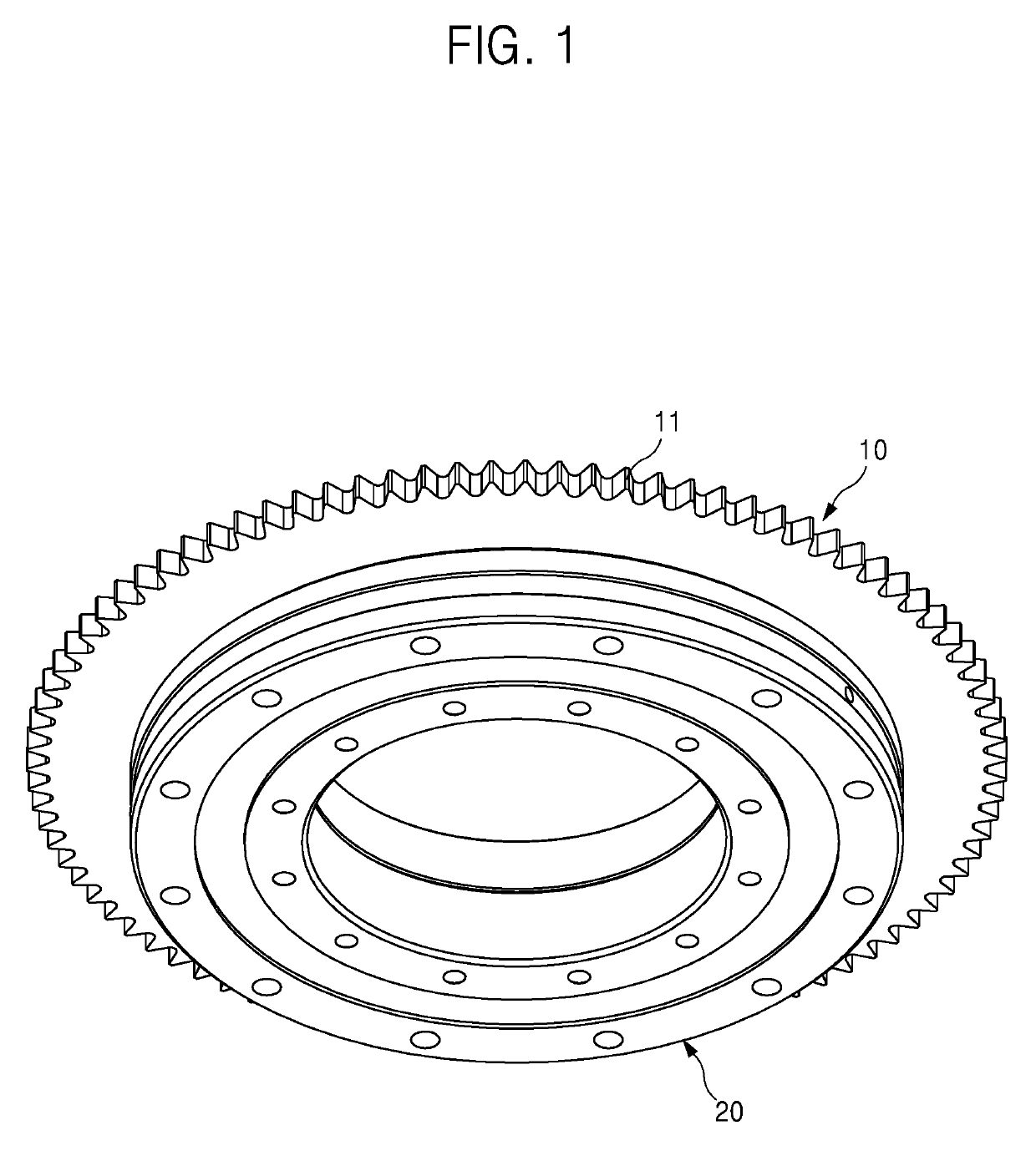
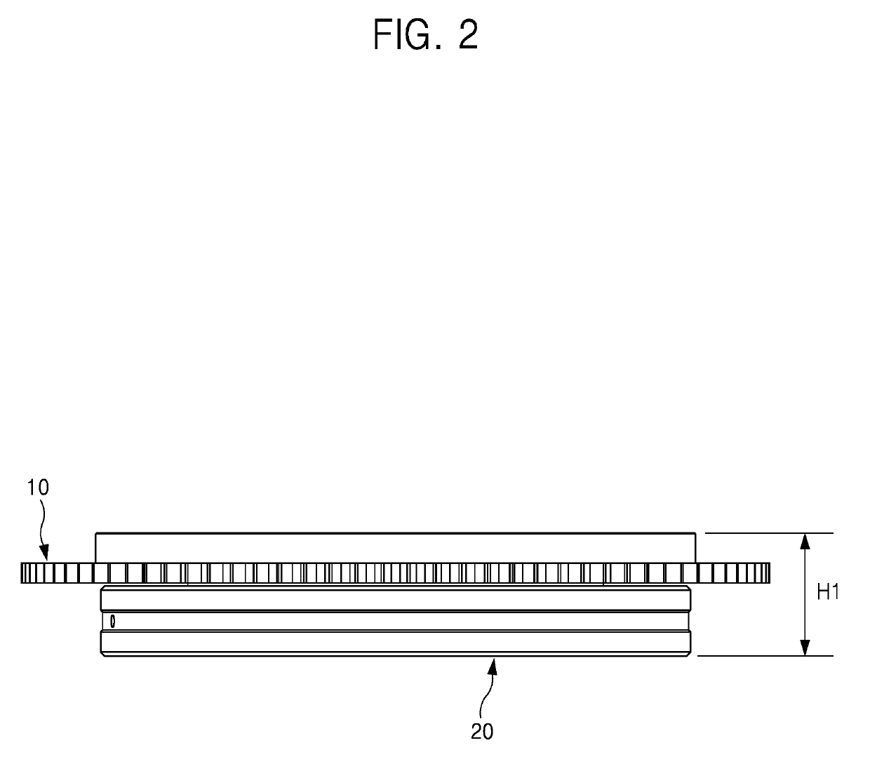
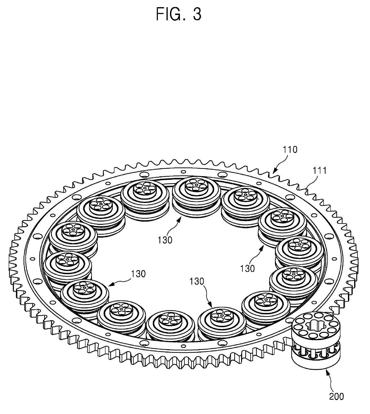
[0016]The present inventive concept provides a module bearing and a power transmission device including the module bearing. The module bearing is applicable to equipment without limitation of the size of a ring gear, may remarkably reduce installation costs by selectively using only a necessary number of module bearings according to a load demanded by a process, may enable thin and light implementation in an axial direction due to a compact structure, and, when a linear gear or a curved gear is used, may smoothly guide linear motion and curved motion of the gear due to an efficient structure.

Advantageous Effects

[0017]According to the present inventive concept, the module bearing is applicable to equipment without limitation of the size of a ring gear, may remarkably reduce installation costs by selectively using only a necessary number of module bearings according to a load demanded by a process, may enable thin and light implementation in an axial direction due to ...


PUM


Abstract

A module bearing and a power transmission device including the module bearing. A module bearing includes a module outer wheel supported by and in contact with a side wall of a gear to guide rotational or linear motion of the gear, a bearing rotor rotatably disposed radially inward of the module outer wheel, and a part-assembly type module inner wheel disposed radially inward of the module outer wheel with the bearing rotor interposed therebetween and connected to the bearing rotor, in which a plurality of separate parts are manufactured and assembled into the part-assembly type module inner wheel to apply a preload to the bearing rotor.

Description

TECHNICAL FIELD[0001]The present inventive concept relates to a module bearing and a power transmission device including the same, and more particularly, to a module bearing which is applicable to equipment without limitation of the size of a ring gear, may remarkably reduce installation costs by selectively using only a necessary number of module bearings according to a load demanded by a process, may enable thin and light implementation in an axial direction due to a compact structure, and, when a linear gear or a curved gear is used, may smoothly guide linear motion and curved motion of the gear due to an efficient structure, and a power transmission device including the same.BACKGROUND ART[0002]Power transmission devices may be applied to various industrial equipment including semiconductor equipment or flat panel display equipment such as LCDs, PDPs, or OLEDs, to implement linear or curved motion. In other words, the power transmission device may implement a linear or curved mo...

Claims


Application Information

Patent Timeline
Patent Type & Authority Applications(United States)
IPC IPC(8): F16C19/08F16C19/36F16C19/54F16C29/00F16C29/04F16H19/04F16H1/10F16H1/06F16H55/10
CPCF16C19/362F16C29/008F16C29/045F16H1/10F16C2361/61F16H55/10F16C2226/60F16C19/08F16H19/04F16C19/547F16H1/06F16C19/166F16C19/183F16C19/507F16C25/06F16C29/001F03D7/0204F03D80/70Y02P70/50F16C2300/14
Inventor LIM, SUN HO
Owner SEJIN IGB
Why Eureka
Try Eureka