Eureka AIR delivers breakthrough ideas for toughest innovation challenges, trusted by R&D personnel around the world.

Wireless passive strain sensor

Active Publication Date: 2019-10-03
NAT CHIAO TUNG UNIV
View PDF8 Cites 0 Cited by
  • Summary
  • Abstract
  • Description
  • Claims
  • Application Information

AI Technical Summary

Benefits of technology

The present invention provides a wireless passive strain sensor with the advantage of space efficiency. The sensor includes a sensing inductance coil and an inner coil holder, which eliminates the need for a battery module and reduces the space requirement.

Problems solved by technology

However, mounting the sensor on the shaft requires a battery or a wireless transmission module, which occupies more spaces, makes connecting lines entangle the shaft when rotating, or requires machining the shaft.
The methods mentioned above would affect the shaft when rotating due to the existence of the sensor, further affecting the results of the measurement.

Method used


Image

  • Wireless passive strain sensor
  • Wireless passive strain sensor
  • Wireless passive strain sensor

Examples


Embodiment Construction

[0027]To facilitate the review of the technique characteristics, contents, advantages, and achievable effects of the present invention, the embodiments together with the drawings are described in detail as follows. However, the drawings are used only for the purpose of indicating and supporting the specification, which is not necessarily the real proportion and precise configuration after the implementation of the present invention. Therefore, the relations of the proportion and configuration of the attached drawings should not be interpreted to limit the actual scope of implementation of the present invention.

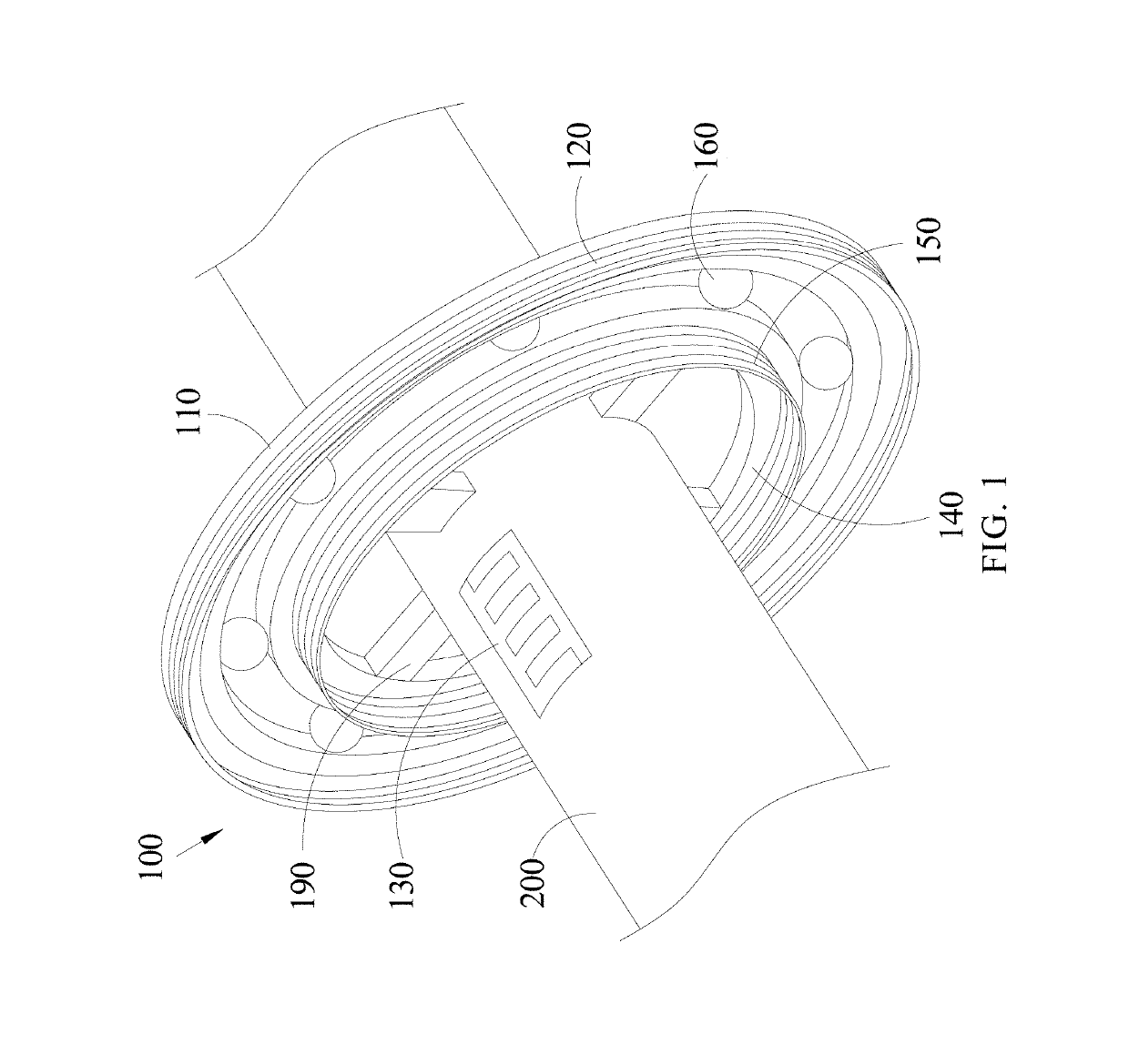
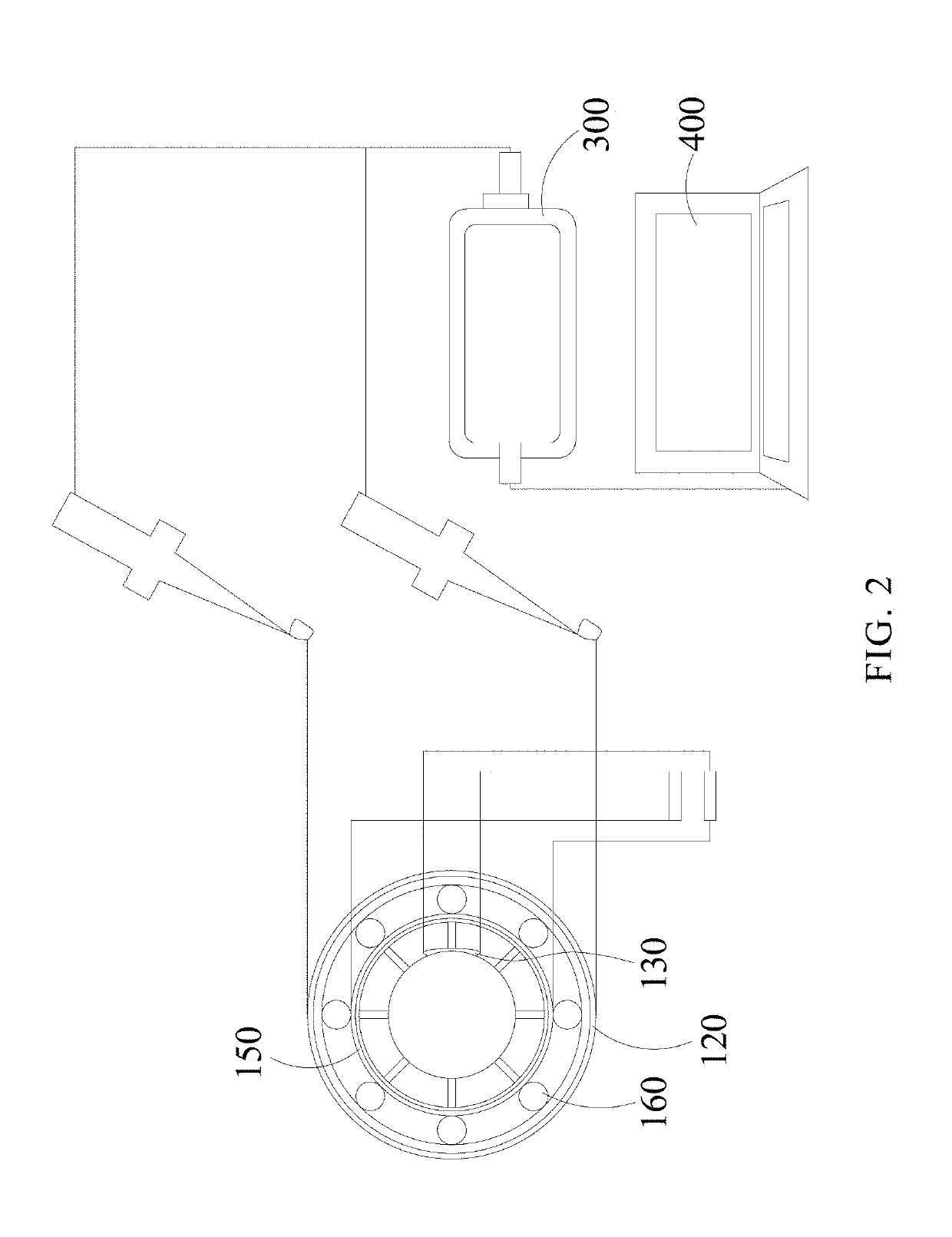
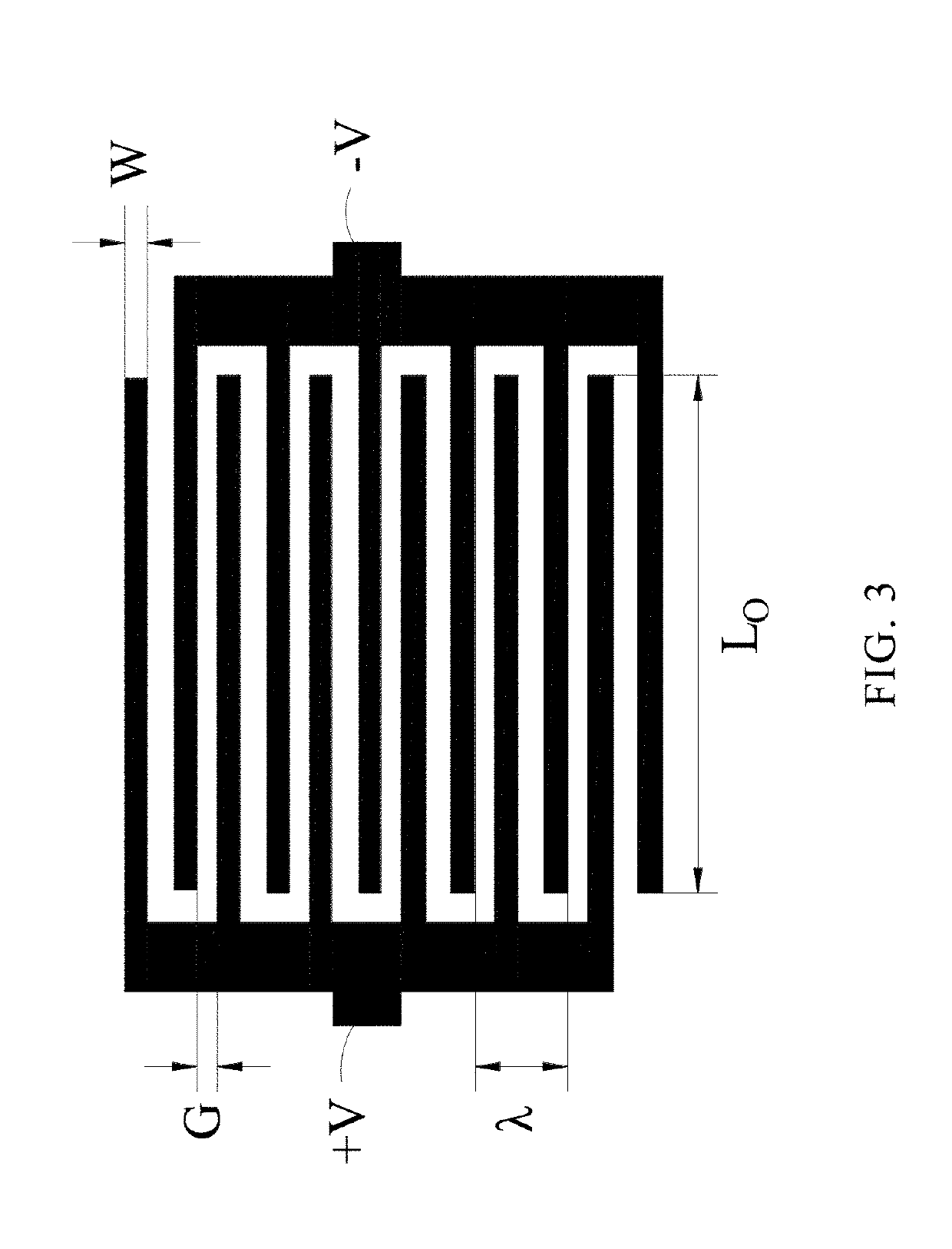
[0028]Please refer to FIGS. 1 to 4. FIG. 1 is a first schematic view of a wireless passive strain sensor of an embodiment in the present invention. FIG. 2 is a second schematic view of a wireless passive strain sensor of an embodiment in the present invention. FIG. 3 is a first schematic view of a capacitance patch of a wireless passive strain sensor of an embodiment in the pr...


PUM


Abstract

A wireless passive strain sensor is provided. The wireless passive strain sensor includes an outer coil holder, a reading inductance coil, a capacitance patch, an inner coil holder, and a sensing inductance coil. A shaft penetrates through the outer coil holder. The reading inductance coil is disposed on the outer coil holder. The capacitance patch is disposed on the shaft. The inner coil holder is disposed inside the outer coil holder. The inner coil holder is disposed on the shaft. The sensing inductance coil is disposed on the inner coil holder. The sensing inductance coil is electrically connected to the capacitance patch.

Description

CROSS-REFERENCE TO RELATED APPLICATION[0001]This application claims the benefit of Taiwan Patent Application No. 107110564, filed on Mar. 27, 2018, in the Taiwan Intellectual Property Office, the disclosure of which is incorporated herein in its entirety by reference.BACKGROUND OF THE INVENTION1. Field of the Invention[0002]The present invention generally relates to a strain sensor, and more particularly to a wireless passive strain sensor able to sense a strain of a shaft.2. Description of the Related Art[0003]Generally, to measure the load on a dynamic rotating shaft, a sensor is usually mounted on the shaft. However, mounting the sensor on the shaft requires a battery or a wireless transmission module, which occupies more spaces, makes connecting lines entangle the shaft when rotating, or requires machining the shaft. The methods mentioned above would affect the shaft when rotating due to the existence of the sensor, further affecting the results of the measurement.SUMMARY OF THE...

Claims


Application Information

Patent Timeline
IPC IPC(8): G01B7/16G01B7/24F16C41/00
CPCF16C41/00F16C2233/00G01B7/24G01B7/22G01B2210/58F16C33/32F16C19/522G01B15/06
Inventor HSU, WEN-SYANGWU, SUNG-YUEHTU, CHENGCHAO, CHIA-MIN
Owner NAT CHIAO TUNG UNIV
Why Eureka
Eureka Blog
Learn More