Method for operating a rotational-speed-variable refrigerant compressor

a technology of rotational speed and variable temperature, which is applied in the field of method for operating a refrigerant compressor, can solve the problems of increasing the energy consumption the evaporator unavoidably heating the refrigerant, and the inability of the electronic control device of the refrigerant compressor to react to any special operating state, etc., to achieve the effect of preventing overheating and being easy to adap

Inactive Publication Date: 2019-10-10
NIDEC GLOBAL APPLIANCE GERMANY GMBH
View PDF0 Cites 3 Cited by
  • Summary
  • Abstract
  • Description
  • Claims
  • Application Information

AI Technical Summary

Benefits of technology

[0065]Normally, electronic control devices are capable of establishing a preceding power outage. However, they are not able to determine how long the power supply was interrupted. If the outage was short, it would not be purposeful to initiate a special cooling cycle, since only a small additional cooling demand exists in the cooled volume. Therefore, a special cooling cycle is only initiated if the electronic control device of the refrigerant compressor has established a power outage and the comparison parameter is exceeded or fallen short of by the currently measured parameter value. In this way, it can be ensured that the special cooling cycle is only initiated when an interruption of the power supply has been established and it has been verified on the basis of the exceeding or falling short of the comparison parameter by the currently measured parameter value that indeed an elevated cooling demand exists in the cooled volume.
[0075]Normally, the electronic control device of the refrigerant compressor already comprises a temperature measuring device for other purposes, for example for monitoring the temperature of the electronic control device to prevent overheating, so that the electronic control device does not become more expensive due to implementation of this aspect of the invention and the measured values of said temperature measuring device can be employed as the additional temperature according to the invention.
[0076]An additional advantage of the use of the measured values of a temperature measuring device already provided in a traditional electronic control device as the additional measured temperature lies in the fact that only the programming of the electronic control device of the refrigerant compressor needs to be altered and not the structure of the electronic control device itself. In this way, refrigerant compressors already in use can be easily adapted for carrying out the method according to the invention.
[0078]In order to enable the detection of a special operating state in a simple way on the basis of a change of the current operating state of the refrigerant compressor without having to rely on a stored comparison parameter that was predefined in the as-supplied state and stored in the control device of the refrigerant compressor, in another preferred embodiment of the method according to the invention it is provided that the at least one measured current parameter value is stored as the stored parameter value in the electronic control device of the refrigerant compressor over at least two operating cycles. This allows a special operating state to be inferred from the development of the stored parameter values. Preferably, the stored parameter values are stored over 3, 4, 5, 8, or 10 operating cycles in order to be able to monitor and model the operating behavior as accurately as possible.
[0086]A preferred embodiment of the method according to the invention calls for the refrigerant compressor to be operated during the special cooling cycle so that the rotary speed does not go below a defined rotary speed until the end of the special cooling cycle, wherein the defined rotary speed is at least 75%, preferably at least 85%, especially preferably at least 90%, in particular between 95% and 100%, of a maximum rotary speed of the refrigerant compressor. A high value of the defined rotary speed, which is to be understood as a minimum rotary speed, with respect to the maximum rotary speed of the refrigerant compressor, ensures the provision of a high cooling capacity or cooling output by the refrigerant compressor. Here, the refrigerant compressor can be operated, for example, at a first defined rotary speed of 95% of the maximum rotary speed over a first defined time period [and] at a second defined rotary speed of 80% of the maximum rotary speed over a second defined time period, wherein the cycles repeat alternatingly until the special cooling cycle ends.
[0090]an electronic control device in accordance with the invention for control of the cyclic operation of the variable-speed refrigerant compressor according to a method according to the invention. Such a module can be easily installed in a refrigeration system without a control unit of the refrigeration system transmitting a control signal or a rotary speed setting to the electronic control device of the refrigerant compressor.

Problems solved by technology

A disadvantage of the control of the prior art lies in the fact that the electronic control device of the refrigerant compressor is not capable of reacting to any special operating states such as an increased cooling demand after a defrost operation or after a power outage.
The refrigerant that is in the evaporator unavoidably becomes heated during the defrost operation.
Another problem in simple refrigeration systems results from the fact that simple refrigeration systems are often operated in regions with weak infrastructure, in which a steady supply of electricity is not guaranteed, rather interruptions of the electricity supply are the order of the day.
This results in the length of the cooling cycle that follows the special operating state being disproportionately higher than the duration of the preceding cooling cycles and an increased energy consumption of the refrigerant compressor resulting from the long duration of the cooling cycle.

Method used


Image

  • Method for operating a rotational-speed-variable refrigerant compressor
  • Method for operating a rotational-speed-variable refrigerant compressor
  • Method for operating a rotational-speed-variable refrigerant compressor

Examples


first embodiment

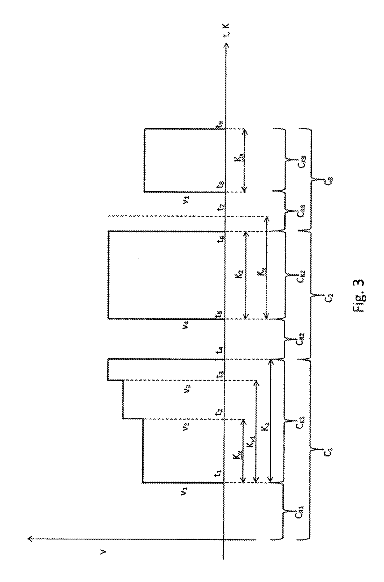
[0097]FIG. 5 shows a schematic representation of the rotary speed behavior after a defrost operation according the method according to the invention;

second embodiment

[0098]FIG. 6 shows a schematic representation of the rotary speed behavior after a defrost operation according to the method according to the invention;

third embodiment

[0099]FIG. 7 shows a schematic representation of the rotary speed behavior after a power outage according to the method according to the invention.

WAYS OF IMPLEMENTING THE INVENTION

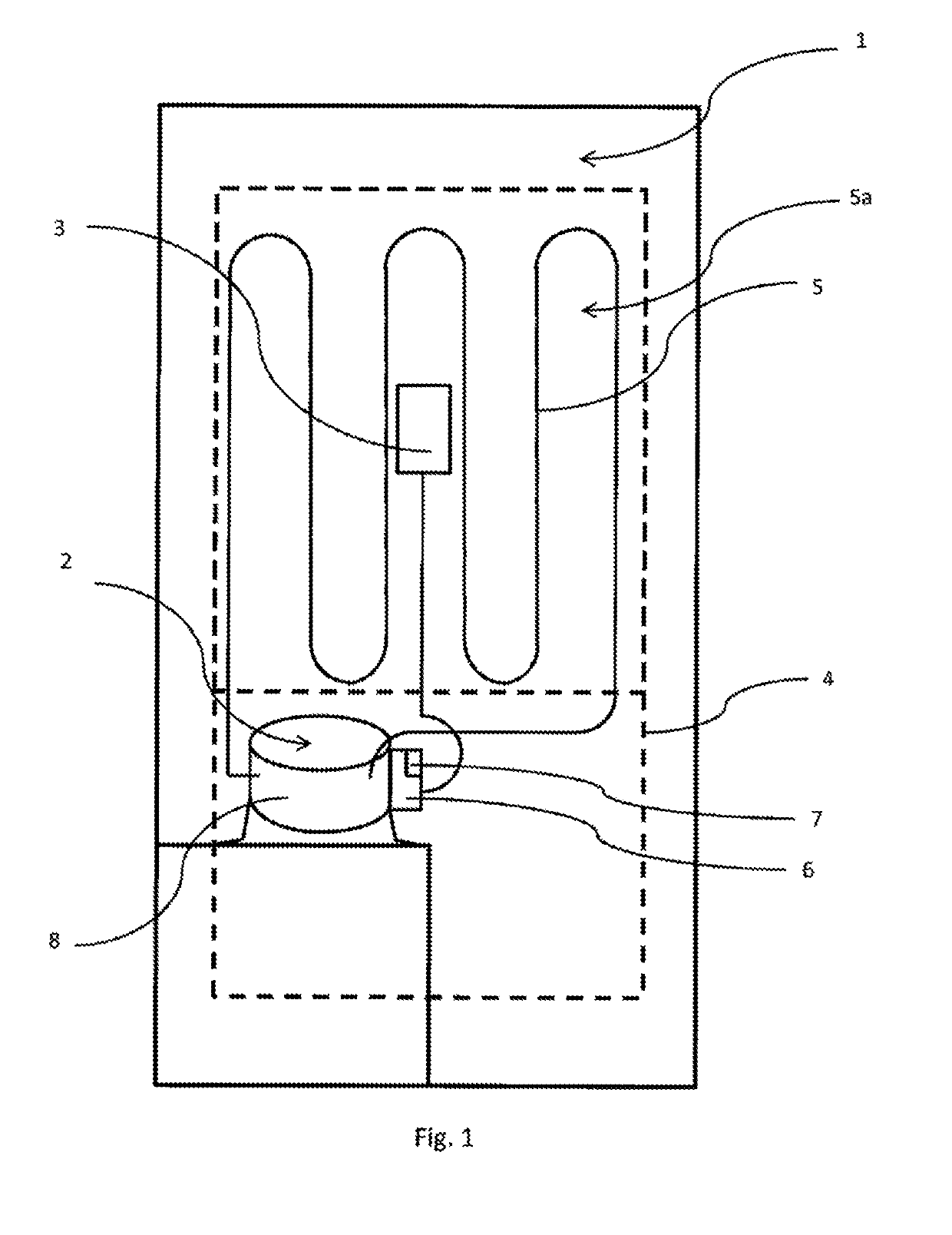
[0100]FIG. 1 shows a simple refrigeration system 1 with a variable-speed refrigerant compressor 2, a refrigerant line 5, and an evaporator 5a. Refrigerant compressor 2, refrigerant line 5, and evaporator 5a form a closed refrigerant system in which refrigerant circulates during the operation, thus during a cooling cycle CK of the refrigerant compressor 2. The refrigeration system 1 has a cooled volume 4, wherein heat can be removed or cooling output delivered by the evaporator 5a by evaporating the refrigerant in evaporator 5a.

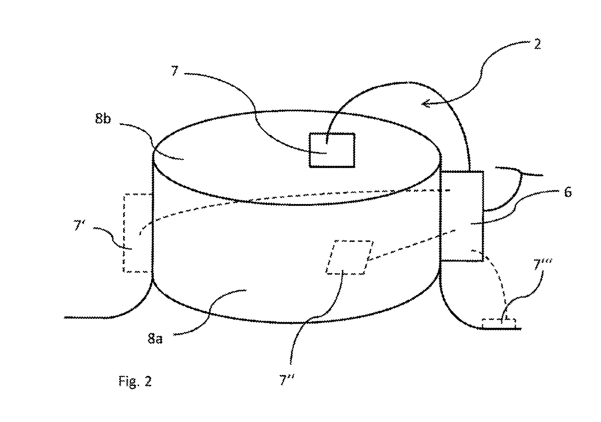
[0101]The individual components of the refrigerant compressor 2, thus at least one piston-cylinder unit in which the refrigerant is cyclically compressed and an electric drive unit, via which the piston-cylinder unit can be driven, are disposed within a housing 8 of the refrigerant...


PUM


Abstract

The invention relates to a method for operating a rotational-speed-variable refrigerant compressor (2) for cooling a cooling volume (4) of a refrigeration system (1), which refrigeration system does not have its own control unit, wherein the refrigeration system (1) comprises at least one thermostat (3) for directly or indirectly monitoring a temperature state of the cooling volume (4) and wherein the rotational-speed behavior of the refrigerant compressor (2) during a cooling cycle is controlled by means of a specification rotational-speed control stored in an electronic control device (6) of the refrigerant compressor (2). According to the invention, in order to enable adjustment of the rotational-speed behavior in reaction to a preceding special operating state and to enable energy-optimized cooling of the cooling volume (4) that is as fast as possible, at least one comparison parameter is stored in the electronic control device (6) of the refrigerant compressor (2) and exceedance or undershooting of the comparison parameter by a current measured parameter value is monitored, a special cooling cycle different from the specification rotational-speed control is triggered if the current measured parameter value exceeds or undershoots the comparison parameter, possibly, a current cooling cycle controlled by means of the specification rotational-speed control is interrupted by the special cooling cycle.

Description

FIELD OF THE INVENTION[0001]The invention concerns a method for operating a refrigerant compressor having a variable rotary speed for cooling a cooled volume of a refrigeration system, wherein the refrigeration system comprises at least one thermostat for direct or indirect monitoring of a temperature state of the cooled volume and wherein the refrigerant compressor is operated cyclically and a cooling cycle of the refrigerant compressor begins when the refrigerant compressor is set to an ON state by a switching signal triggered by the thermostat, and the cooling cycle ends when the refrigerant compressor is set to an OFF state by another switching signal triggered by the thermostat, wherein an operating cycle comprises, in addition to the cooling cycle, a rest cycle that follows the cooling cycle, and wherein the rotary speed behavior of the refrigerant compressor is controlled during a cooling cycle by means of a preset rotary speed control that is stored in an electronic control ...

Claims


Application Information

Patent Timeline
Patent Type & Authority Applications(United States)
IPC IPC(8): F25B47/02F25B49/02
CPCF25B49/022F25B47/02F25B2700/2106F25B2600/0253F25B2700/21153F25B2700/151Y02B30/70F24F11/37F24F11/64F24F11/65
Inventor GRIES, ULRICHGLÄSER, JÜRGEN EWALDSLOT, ALLAN HAUEFOGH, HANS-ERIK
Owner NIDEC GLOBAL APPLIANCE GERMANY GMBH
Why Eureka
Try Eureka