Supercharge Your Innovation With Domain-Expert AI Agents!

Light guides with coating to be used in water

Active Publication Date: 2019-10-10
KONINKLJIJKE PHILIPS NV
View PDF2 Cites 1 Cited by
  • Summary
  • Abstract
  • Description
  • Claims
  • Application Information

AI Technical Summary

Benefits of technology

The patent text describes a method to prevent biofouling on surfaces in contact with sea water or other water sources using UV radiation. The approach involves using a two-dimensional grid of light sources to generate UV light that can kill micro-organisms. The light sources may be arranged in a regular or irregular structure, and their physical distance from each other can vary based on requirements. The UV radiation is distributed close to the areas to be protected, reducing energy waste and promoting homogeneity of the light distribution. Overall, the method offers an effective and efficient solution for preventing biofouling on water surfaces.

Problems solved by technology

In several circumstances biofouling creates substantial problems.
Machinery stops working, water inlets get clogged, and hulls of ships suffer from increased drag.
Biofouling on the hull of ships causes a severe increase in drag, and thus increased fuel consumption.
It appears that most micro-organisms are killed, rendered inactive or unable to reproduce with sufficient UV light.
A common problem with light guides is that too much light may escape at some parts, and too little may escape at other parts, which may lead to a sub-optimal distribution of the escaped light.
However, this may include additional optical elements, which may make the module more expensive and may make the production process more complex.

Method used


Image

  • Light guides with coating to be used in water
  • Light guides with coating to be used in water
  • Light guides with coating to be used in water

Examples


Embodiment Construction

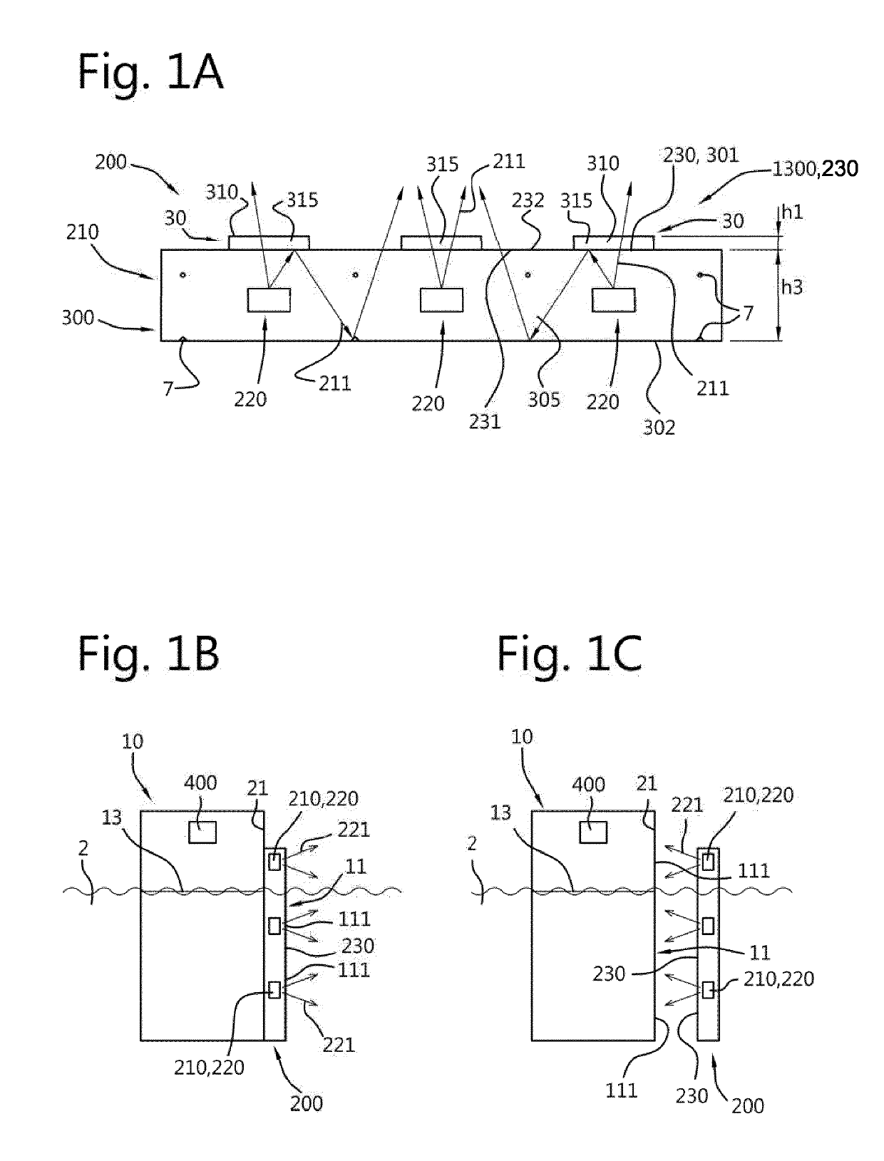
[0135]FIG. 1a schematically depicts an embodiment of an anti-biofouling system 200 which comprises an UV-emitting element 210. The UV-emitting element 210 comprises a UV radiation exit window 230. The UV-emitting element 210 at least partly encloses a light source 220 configured to provide UV radiation 221 (anti-fouling light). Here, by way of example three light sources 220 are depicted. Here, the UV-emitting element 210 is configured as waveguide or light guide, with elements embedded therein. Hence, the light sources 220 are—in this schematically depicted embodiment—embedded in the waveguide. The UV radiation exit window 230 is configured to transmit at least part of the UV radiation 221 of the light source 220. The UV radiation exit window 230 comprises an upstream window side 231, here directed to the light source(s) and a downstream window side 232. In FIG. 1a, a light guide element 1300 comprising a light guide 300 or optical medium and a first layer element 30 is schematical...


PUM


Abstract

The invention provides a light guide element (1300) comprising a light guide (300), wherein the light guide (300) in comprises a first light guide face (301) and a second light guide face (302) with UV radiation transmissive light guide material (305) between the first light guide face (301) and the second light guide face (302), wherein the light guide element (1300) further comprises one or more of: (i) a first layer element (30) in contact with the first light guide face (301), wherein the first layer element (30) is transmissive for UV radiation; and (ii) a second layer element (130) in contact with the second light guide face (301), wherein the second layer element (130) has one or more functionalities selected from the group consisting of (a) reflective for UV radiation, (b) adhesive for adhering the light guide (300) to an object, (c) reinforcing the light guide element (1300), and (d) protective for the light guide (300).

Description

FIELD OF THE INVENTION[0001]The invention relates to a light guide element. The invention further relates to an anti-biofouling system comprising such light guide element. The invention also relates to an object that during use may at least partly be submerged in water, especially a vessel or an infrastructural object, which includes such anti-biofouling system. Further, the invention relates to a method for providing such anti-biofouling system to an object, especially a vessel or an infrastructural object. Yet further, the invention also provides a method of preventing and / or reducing biofouling at an external surface of an object.BACKGROUND OF THE INVENTION[0002]Anti-biofouling methods are known in the art. US2013 / 0048877, for instance, describes a system for anti-biofouling a protected surface, comprising an ultraviolet light source configured to generate ultraviolet light, and an optical medium disposed proximate to the protected surface and coupled to receive the ultraviolet l...

Claims


Application Information

Patent Timeline
IPC IPC(8): F21V8/00C02F1/32A61L2/10
CPCC02F2303/20C02F2201/3228G02B6/0065A61L2/10G02B6/0055A61L2202/11C02F1/325G02B6/0018G02B6/102G02B6/0031G02B6/0066B08B17/02B63B59/04B63B59/08B08B7/0057B63B59/06
Inventor HIETBRINK, ROELANT BOUDEWIJNSALTERS, BART ANDREDE WIJS, WILLEM-JAN AREND
Owner KONINKLJIJKE PHILIPS NV
Features
  • R&D
  • Intellectual Property
  • Life Sciences
  • Materials
  • Tech Scout
  • Unparalleled Data Quality
  • Higher Quality Content
  • 60% Fewer Hallucinations
Learn More