Rope and elevator using same
a technology of rope and elevator, which is applied in the direction of elevators, transportation and packaging, etc., can solve the problems of reducing the weight of a related-art rope including a load supporting member, and becoming more difficult to secure the safety of the rope, so as to reduce the bending rigidity, increase the strength, and reduce the weight
- Summary
- Abstract
- Description
- Claims
- Application Information
AI Technical Summary
Benefits of technology
Problems solved by technology
Method used
Image
Examples
first embodiment
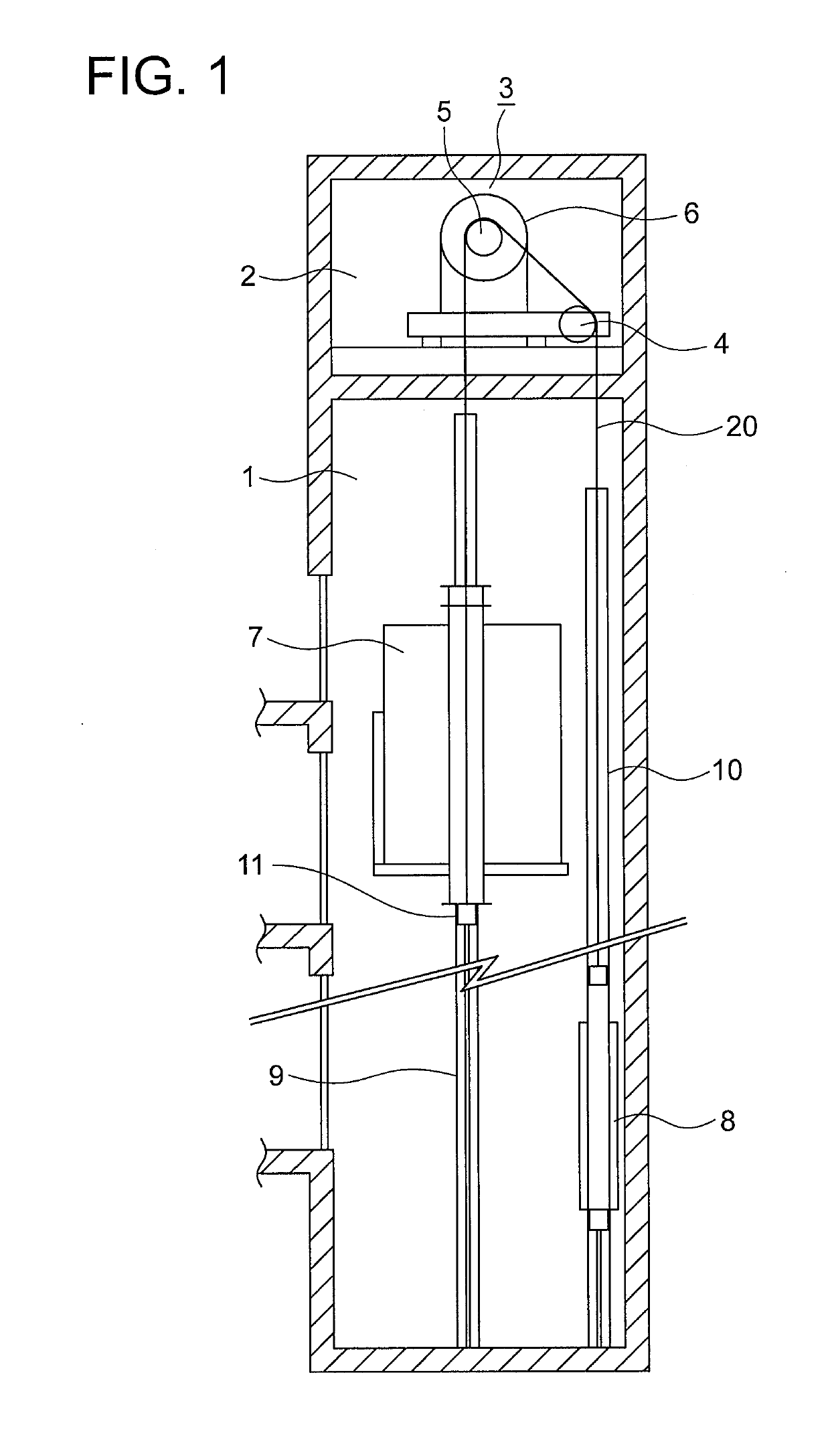
[0034]FIG. 1 is a configuration view for illustrating an elevator according to a first embodiment of this invention. In FIG. 1, a machine room 2 is provided in an upper part of a hoistway 1. In the machine room 2, there are installed a hoisting machine 3 and a deflector sheave 4. The hoisting machine 3 includes a drive sheave 5 and a hoisting machine main body 6. In the hoisting machine main body 6, there are provided a hoisting machine motor (not shown), which is configured to rotate the drive sheave 5, and a hoisting machine brake (not shown), which is configured to brake the rotation of the drive sheave 5.
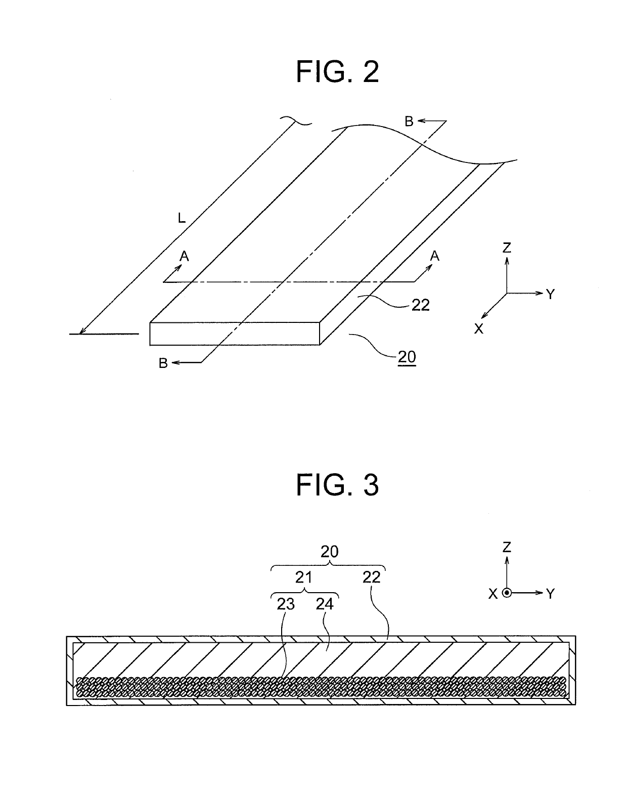
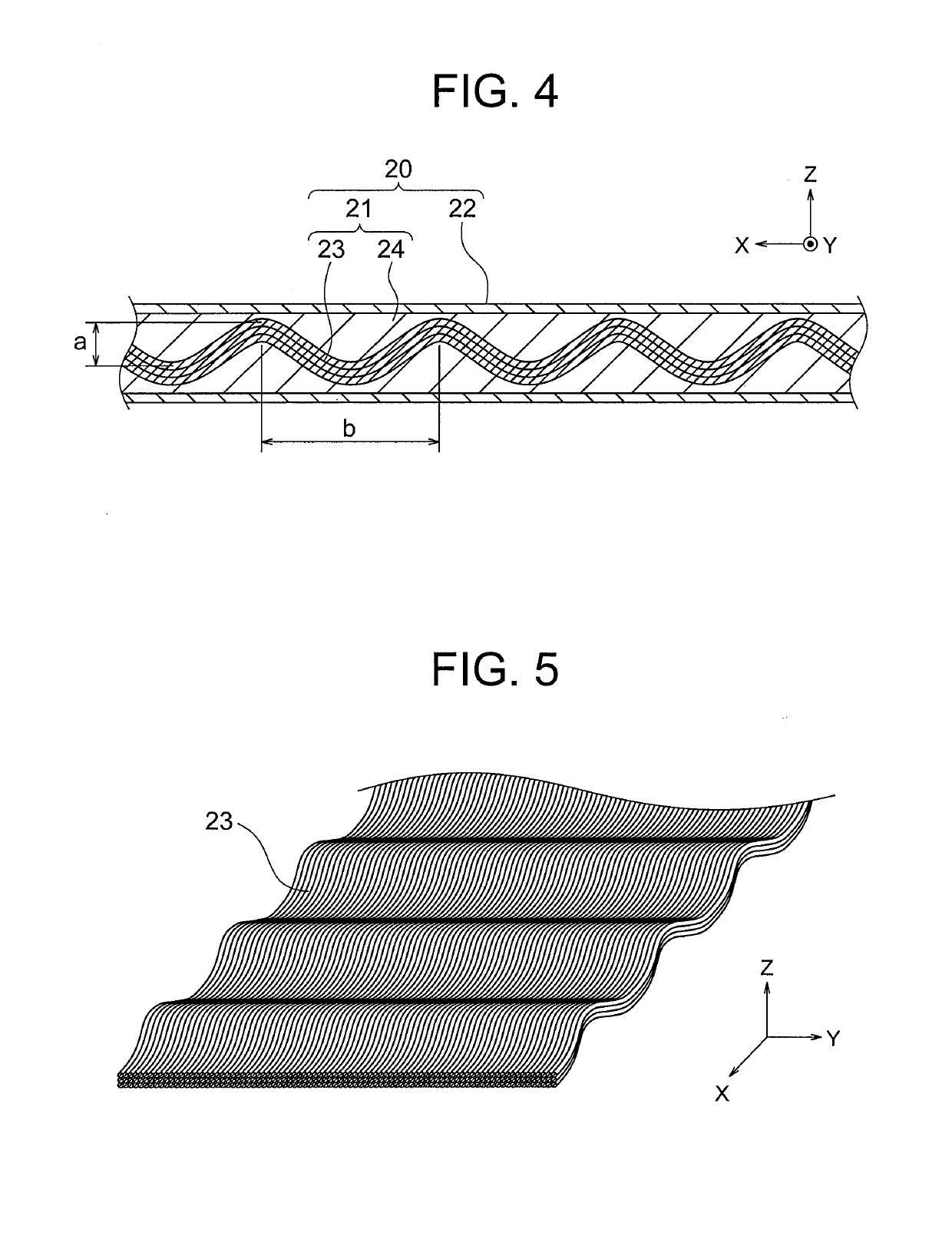
[0035]A plurality of (only one is illustrated in FIG. 1) ropes 20 are wound around the drive sheave 5 and the deflector sheave 4. A car 7 is connected to a first end portion of the rope 20 in the longitudinal direction. A counterweight 8 is connected to a second end portion of the rope 20 in the longitudinal direction. The car 7 and the counterweight 8 are suspended by the rope ...
second embodiment
[0078]Next, FIG. 7 is an A-A sectional view of FIG. 2 of the rope 20 according to a second embodiment of this invention. FIG. 8 is a B-B sectional view of FIG. 2 of the rope 20 of FIG. 7. The load supporting member 21 in the second embodiment further includes a plurality of rod-shaped cross members 26. The cross members 26 are spaced apart from each other in the longitudinal direction of the load supporting member 21 and are embedded in the impregnation material 24.
[0079]Moreover, the cross members 26 are arranged in parallel with each other and in parallel with the Y-axis direction. Further, the cross members 26 each have an elongated shape extending in a direction perpendicular to the longitudinal direction of the load supporting member 21. Furthermore, the cross members 26 each have a circular sectional shape. The cross members 26 each have an elastic modulus larger than an elastic modulus of the impregnation material 24. Moreover, it is desired that the cross members 26 be preve...
third embodiment
[0098]Next, FIG. 11 is an A-A sectional view of the rope 20 according to a third embodiment of this invention. FIG. 12 is a B-B sectional view of the rope 20 of FIG. 11. FIG. 13 is a perspective view for illustrating only the corrugated reinforcement fiber bundles 23 and the cross members 26 taken out from the rope 20 of FIG. 11.
[0099]In the third embodiment, the corrugated reinforcement fiber bundles 23 are divided into a plurality of groups arrayed in the width direction of the load supporting member 21. The corrugated reinforcement fiber bundles 23 in the groups adjacent to each other in the width direction of the load supporting member 21 are deviated by 180° in phase in the longitudinal direction of the load supporting member 21 and are wound around the cross members 26.
[0100]In this example, the corrugated reinforcement fiber bundles 23 are divided into different groups each including one corrugated reinforcement fiber bundle 23. Therefore, the corrugated reinforcement fiber b...
PUM
| Property | Measurement | Unit |
|---|---|---|
| friction coefficient | aaaaa | aaaaa |
| strength-to-weight ratio | aaaaa | aaaaa |
| shape | aaaaa | aaaaa |
Abstract
Description
Claims
Application Information
 - R&D
- Intellectual Property
- Life Sciences
- Materials
- Tech Scout
- Unparalleled Data Quality
- Higher Quality Content
- 60% Fewer Hallucinations
Browse by: Latest US Patents, China's latest patents, Technical Efficacy Thesaurus, Application Domain, Technology Topic, Popular Technical Reports.
© 2025 PatSnap. All rights reserved.Legal|Privacy policy|Modern Slavery Act Transparency Statement|Sitemap|About US| Contact US: help@patsnap.com


