
Teleconverter lens and electronic device including same
a technology of electronic devices and teleconverters, which is applied in the direction of optics, instruments, optical elements, etc., can solve the problems of magnification curvature, difficulty in correcting magnification chromatic aberration, etc., and achieves the effect of reducing the size of the outer diameter, facilitating aberration correction, and increasing the focal length
Patent Information
- Authority / Receiving Office
- US · United States
- Current Assignee / Owner
- Publication Date
- 2019-10-17
- Estimated Expiration
- Not applicable · inactive patent
Smart Images
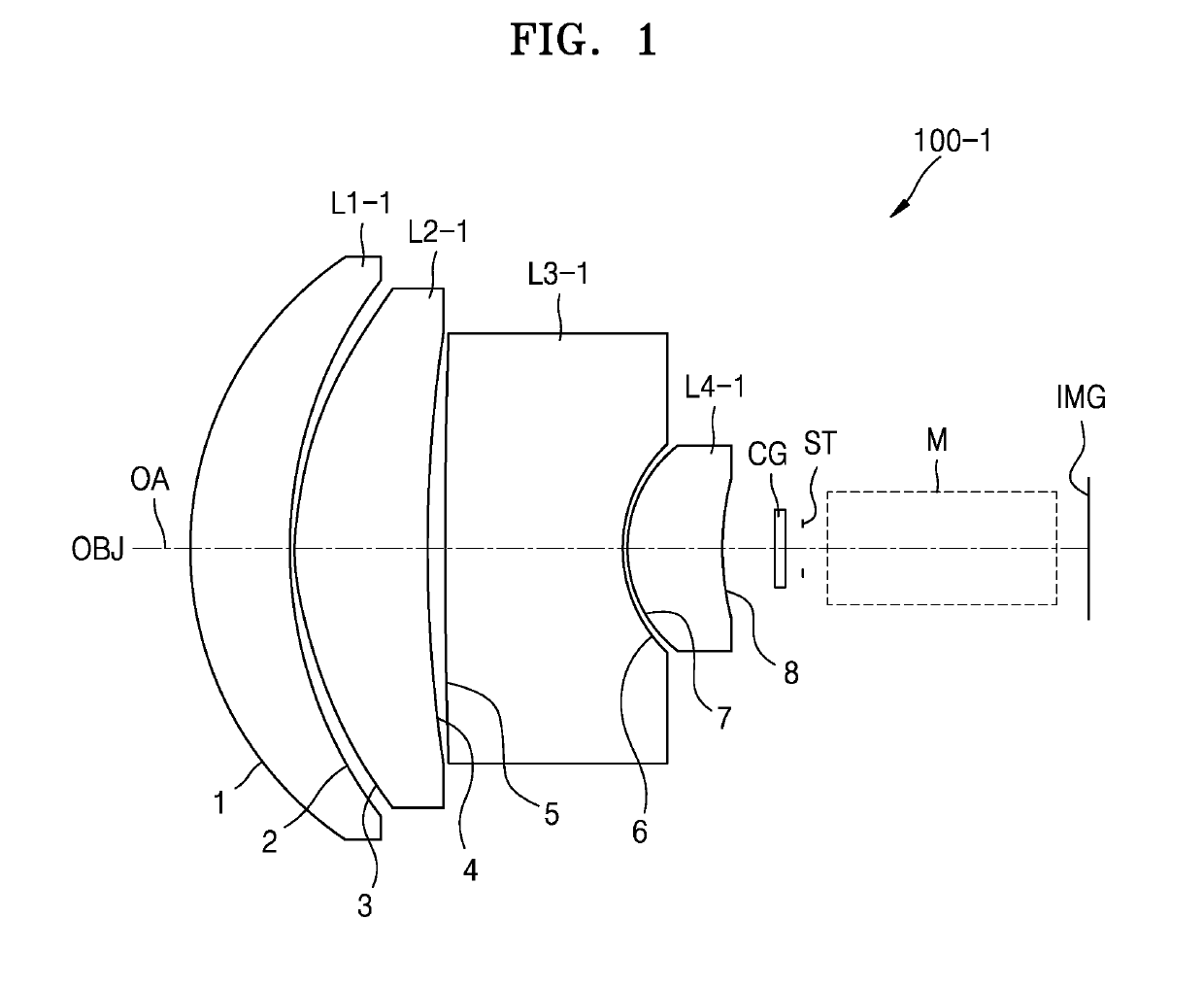
Figure 1 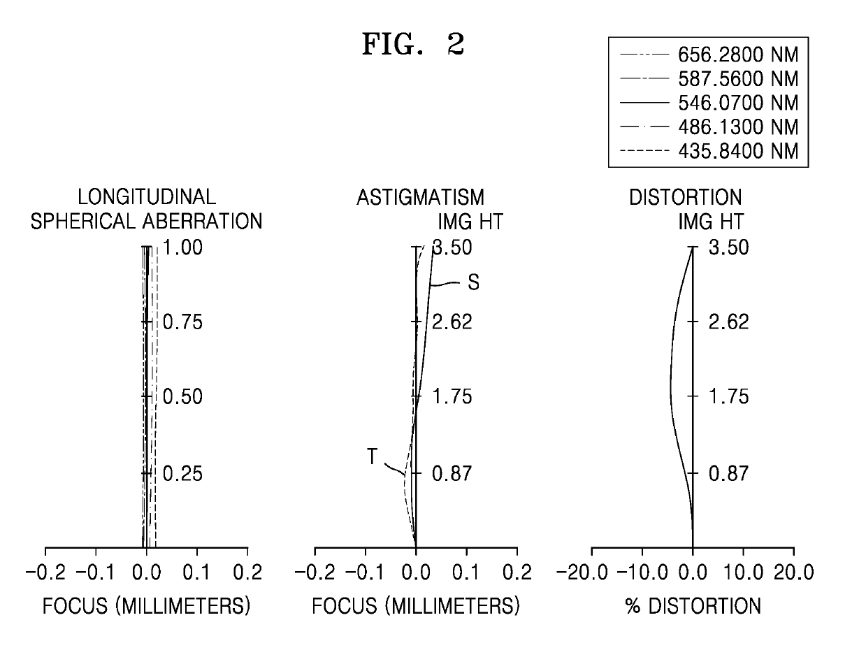
Figure 2 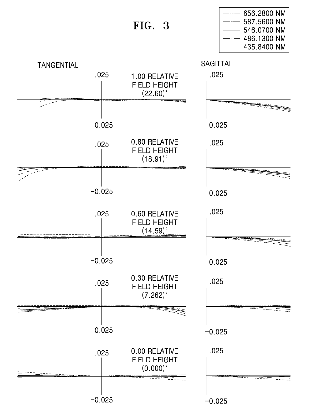
Figure 3
Abstract
Description
TECHNICAL FIELD
[0001] The present disclosure relates to a tele-converter lens and an electronic device including the tele-converter lens, for example, a miniaturized tele-converter lens without optical performance degradation and an electronic device including the miniaturized tele-converter lens.BACKGROUND ART
[0002] The variety of services and additional functions provided by electronic devices are gradually expanding. An electronic device, for example, a mobile device or a user device, may provide various services through various sensor modules. An electronic device may provide a multimedia service, for example, a photo service or a video service. As the use of electronic devices increases, the use of cameras functionally linked with electronic devices is also increasing. The camera performance and / or resolution of electronic devices are being improved according to the demand of users. With cameras of electronic devices, pictures of various landscapes, people, or self-shots may be t...
Examples
first numerical example
[0088]FIG. 1 illustrates the tele-converter lens 100-1 of the first numerical example according to various embodiments, and Table 1 shows, for example, the design data of the first numerical example.
TABLE 1SurfaceRadius ofThickness orNumberCurvatureDistancendVd117.444.96631.51664.2222.3590.23*14.4856.5841.53155.914*36.880.8475291.9728.851.846623.7867.1630.2297*9.0464.781.642822.48*38.536
[0089]Table 2 shows aspherical surface coefficients in the first numerical example.
TABLE 2Surface NumberKABCD3−0.36668−8.67E−05−8.46E−081.70E−09−2.55E−124−99−4.70E−05 4.31E−071.23E−09−1.16E−1171.56758 9.79E−04−1.94E−054.36E−07 2.56E−09892.18057 1.52E−03−1.06E−047.91E−06−1.44E−07
[0090]FIG. 2 illustrates longitudinal spherical aberration, astigmatism, and distortion of the tele-converter lens 100-1 according to the first numerical example. The longitudinal spherical aberration is shown, for example, for light having wavelengths of 656.2800 nanometers (NM), 587.5600 NM, 546.0700 NM, 486.1300 NM, and 435...
second numerical example
[0092]FIG. 4 illustrates the tele-converter lens 100-2 of the second numerical example according to various embodiments, and Table 3 shows, for example, the design data of the second numerical example.
TABLE 3SurfaceRadius ofThickness orNumberCurvatureDistancendVd123.7343.8151.77249.6224.8540.253*19.338.7721.54456.14*95.9150.535*44.7396.9981.64222.46*11.6183.934744.5218.81.72828.38−10.1491.52.00129.139−544.37
[0093]Table 4 shows aspherical surface coefficients in the second numerical example.
TABLE 4Surface NumberKABCD3−1.21977 1.58E−06 1.15E−08 5.23E−119.12E−144−7.20636 5.85E−06 2.63E−08 2.19E−11−3.25E−13 5−7.96762−7.74E−06−1.56E−09−4.89E−119.74E−156−2.79707−3.17E−05−2.82E−07−7.29E−106.27E−12
[0094]FIG. 5 illustrates longitudinal spherical aberration, astigmatism, and distortion of the tele-converter lens 100-2 according to the second numerical example.
[0095]FIG. 6 illustrates transverse chromatic aberration of the tele-converter lens 100-2 according to the second numerical example.
third numerical example
[0096]FIG. 7 illustrates the tele-converter lens 100-3 of the third numerical example according to various embodiments, and Table 5 shows, for example, the design data of the third numerical example.
TABLE 5SurfaceRadius ofThickness orNumberCurvatureDistancendVd116.897.61.589161.25283.2981.2673*26.9194.51.642822.394*13.2532.305517.6165.6591.784725.726−17.6160.82.00129.1375.780.85287.3031.591.5814440.599−80.428
[0097]Table 6 shows aspherical surface coefficients in the third numerical example.
TABLE 6SurfaceNumberKABCD3−16.1641−1.48E−048.55E−07−3.16E−095.39E−124−9.32523−1.50E−043.37E−07 3.04E−10
[0098]FIG. 8 illustrates longitudinal spherical aberration, astigmatism, and distortion of the tele-converter lens 100-3 according to the third numerical example.
[0099]FIG. 9 illustrates transverse chromatic aberration of the tele-converter lens 100-3 according to the third numerical example.
[0100]Table 7 shows optical specifications, such as the total thickness TT on the optical axis of each of ...