
Electric vehicle battery cell with sense tabs

Active Publication Date: 2019-10-17
VOLKSWAGEN AG +2
View PDF1 Cites 0 Cited by
  • Summary
  • Abstract
  • Description
  • Claims
  • Application Information

AI Technical Summary

Benefits of technology

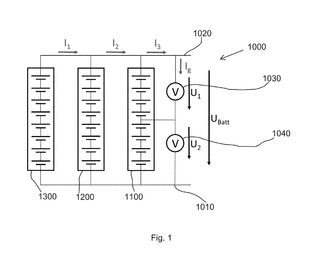
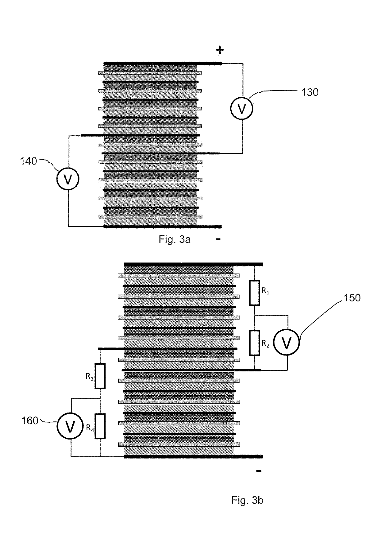
The patent describes a way to monitor individual battery cells using a few voltsmeters, instead of using many sensors for each cell. This reduces costs and simplifies the process of identifying any issues that might arise. By using a second voltsmeter, the location of any issues can be further identified. Overall, this method allows for effective monitoring of battery cells without adding too much complexity or cost.

Problems solved by technology

As disclosed in the patent, if unevenness occurs in voltage between respective unit cell layers, a probability arises wherein one unit cell layer results in an overcharging state and the other unit cell layer results in an over-discharging state with a resultant difficulty in achieving stable use.
As a result, deterioration proceeds from the unit cell whose shared voltage is high and it is conceivable that a life cycle of the stack type battery tends to be limited by the unit cell having such a high shared voltage.

Method used


Image

  • Electric vehicle battery cell with sense tabs
  • Electric vehicle battery cell with sense tabs
  • Electric vehicle battery cell with sense tabs

Examples


second embodiment

[0046]FIG. 5 shows a schematic of a battery 500 according to the present invention. To allow for more precise identification of an issue, two sense tabs can be provided for a battery cell 510, 512, 514, and two voltmeters can be provided for each battery cell 510, 512, 514. In a battery cell with 200 battery cell components, voltmeter 520 for example can monitor the first 110 battery cell components for a voltage U1, and voltmeter 530 the last 91 battery cell component for a voltage U2, overlapping one battery cell component. The part of the battery cell 510 monitored by each voltmeter that malfunctions can be identified, for example by comparing the results from the voltmeters with other battery cells 512, 514 or from stored data such as previous readings of U1 or U2. Even if the overlapped battery cell component malfunctions, the voltage drop for each of the U1 and U2 can be identified by the BMS.

third embodiment

[0047]FIG. 6 shows a schematic of a battery 600 according to the present invention in which three battery cell components of battery cell 610 are overlapped by voltmeters 620, 630. Malfunctions within the battery component areas measured by the voltmeters 620, 630 can be monitored by the BMS. FIG. 6 is provided to show that the number of overlapped components can be more than one, and these overlapped cells function as an isolator for the voltmeters.

fourth embodiment

[0048]FIG. 7 shows a schematic of a battery 700 according to the present invention, with battery cells 710, 712, 714. Here two voltmeters 720, 730 are provided without overlapping, but still permit identification of an issue within their specific measured region, with the top cell functioning as an isolator for voltmeters 720 and 730. The number of cells in this embodiment at the top could be more than one.


PUM


Abstract

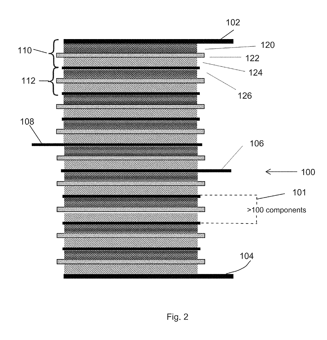
A battery includes a first battery cell including an endplate current collector cathode, an endplate current collector anode, a plurality of battery cell components between the endplate current collector cathode and the endplate current collector anode, each battery cell component including a cathode, a separator, an anode and a bipolar current collector, and at least one sense tab connected to and extending from one of the bipolar current collectors between the endplate current collector cathode and the endplate current collector anode. A second battery cell is connected in parallel to the first battery cell via the endplate current collector cathode and the endplate current collector anode. A voltmeter is connected between a first sense tab and one of the following: the endplate current collector cathode, endplate current collector anode or a second sense tab of the at least one sense tabs, the voltmeter being electrically isolated from at least one of the endplate current collector cathodes and the endplate current collector anodes via at least one battery cell component of the first battery cell and measuring at least two of the battery cell components. A battery cell, a method, an electric vehicle battery and an electric vehicle are also provided.

Description

FIELD OF THE INVENTION[0001]The present invention relates generally to electric vehicles and more particularly to batteries for electric or hybrid vehicles.BACKGROUND[0002]European Patent EP 1 487 034 B1 discloses a battery of a bipolar structure with the detection tabs. As disclosed in the patent, if unevenness occurs in voltage between respective unit cell layers, a probability arises wherein one unit cell layer results in an overcharging state and the other unit cell layer results in an over-discharging state with a resultant difficulty in achieving stable use. By utilizing the detection tabs, as voltage detection tabs for detecting the terminal voltage of each unit cell layer, which is connected to an appropriate external control circuit (such as a voltage detection circuit or an electric current bypass circuit) through leads in use, the voltage for each unit cell layer can be monitored. Additionally, letting charging current or discharging current of the unit cell layer, whose ...

Claims


Application Information

Patent Timeline
IPC IPC(8): H01M10/44H01M10/48H01M10/42B60L50/64
CPCH01M10/425H01M10/441H01M10/482H01M2220/20H01M2010/4271H01M10/0418H01M10/0585H01M2200/00H01M2220/10Y02E60/10Y02P70/50H01M50/249B60L50/64H01M50/204Y02T10/70
Inventor HERRMANN, MIRKOSPEIDEL, ANGELA
Owner VOLKSWAGEN AG
Learn More