Washing machine

a technology of washing machine and nozzle, which is applied in the field of washing machines, can solve the problems of restricted spraying direction, uneven washing of laundry, and remarkable improvement of performance that cannot be expected with a conventional structure, and achieve the effect of uniform washing of laundry and simplified flow path structur

Pending Publication Date: 2019-10-24
LG ELECTRONICS INC
View PDF0 Cites 5 Cited by
  • Summary
  • Abstract
  • Description
  • Claims
  • Application Information

AI Technical Summary

Benefits of technology

[0180]In the washing machine of the present invention, since the transfer conduit forming the nozzle water supply pipe is disposed in the outer circumferential portion of the gasket, the circulating water sprayed from the plurality of nozzles is prevented from reaching the transfer conduit, and therefore, the outer circumferential surface of the transfer conduit can be kept clean.
[0181]In addition, since the transfer conduit is installed outside the gasket, it is easy to separate the transfer conduit for maintenance repair.
[0182]In addition, since the transfer conduit is installed outside the gasket, it is not interfered with the door.
[0183]Further, since the water discharged from the tub is guided to the plurality of nozzles through a single common nozzle water supply pipe, there is an effect that the flow path structure for supplying water to the plurality of nozzles is simplified.
[0184]In addition, even if permeation washing is performed in a state in which a large amount of laundry is put in, the water sprayed from the nozzle can evenly wet the laundry.
[0185]In order to accomplish the above object, the washing machine according to the present invention may spray fluid with various degrees toward the inside of the drum by an annular flow path which is separately installed in the outer side of the gasket.

Problems solved by technology

However, since such a conventional washing machine usually includes a single or two nozzles, not only in the case of the single nozzle but also in the case of the two nozzles, the spraying direction is restricted, so that the laundry is not wet evenly.
In particular, in recent years, although new technologies for controlling the rotation of the drum have been developed in order to impart variety to the flow of laundry put into the drum, there is a limit in that a remarkable improvement in performance cannot be expected with a conventional structure.
Conventionally, when two nozzles are provided, two circulation pipes connected to the circulation pump and two nozzle water supply pipes connected respectively to the two circulation pipes are required, so that the structure of the product is complicated, and the manufacturing process of the product is cumbersome due to the process of assembling the circulation pipes and the nozzle water supply pipes.
In addition, since there are many connection portions between the circulation pipe, the nozzle water supply pipes, and the nozzles, there is a possibility that water may leak from the connection portions during operation of the washing machine.
Particularly, since the outer circumferential surface of the nozzle water supply pipe is wet by the circulating water current sprayed from the nozzle, there is a problem that hygiene problems occur due to the coagulation of the detergent contained in the circulating water and the deposition of contaminants.
However, since the conventional washing machine usually has only one or two nozzles, the direction of spraying the fluid sprayed into the drum is restricted, so that there is a problem in that the fluid cannot be uniformly sprayed to the laundry contained in the drum.
In this case, since the circulation pipe connected to the circulation pump and the nozzle water supply pipe connected to the circulation pipe are separately required, there is a problem in that the structure of the product is complicated and the manufacturing process is increased.
However, since such a conventional washing machine usually has one or two nozzles, the direction of spraying through the nozzles is restricted, so that the laundry cannot be wet evenly.
In recent years, although new technologies for controlling the rotation of the drum have been developed in order to impart variety to the flow of laundry put into the drum, there is a limit in that a remarkable improvement in performance cannot be expected under the conventional nozzle structure.

Method used


Image

  • Washing machine
  • Washing machine
  • Washing machine

Examples


first embodiment

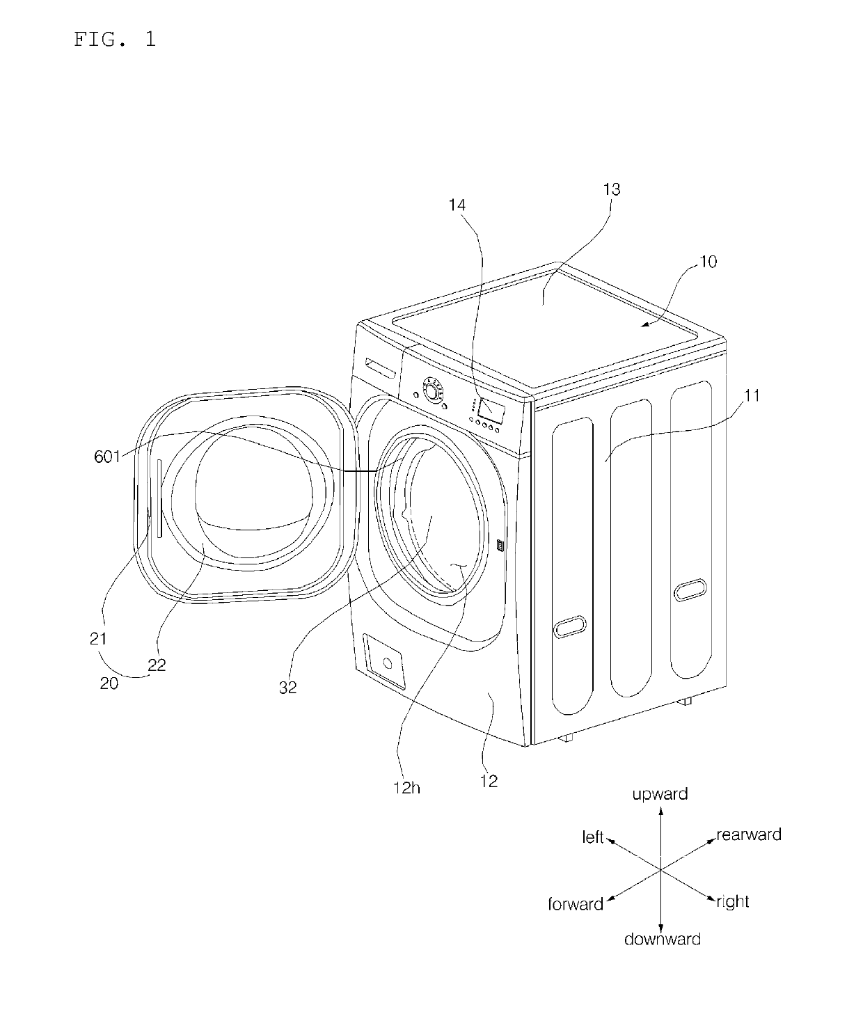
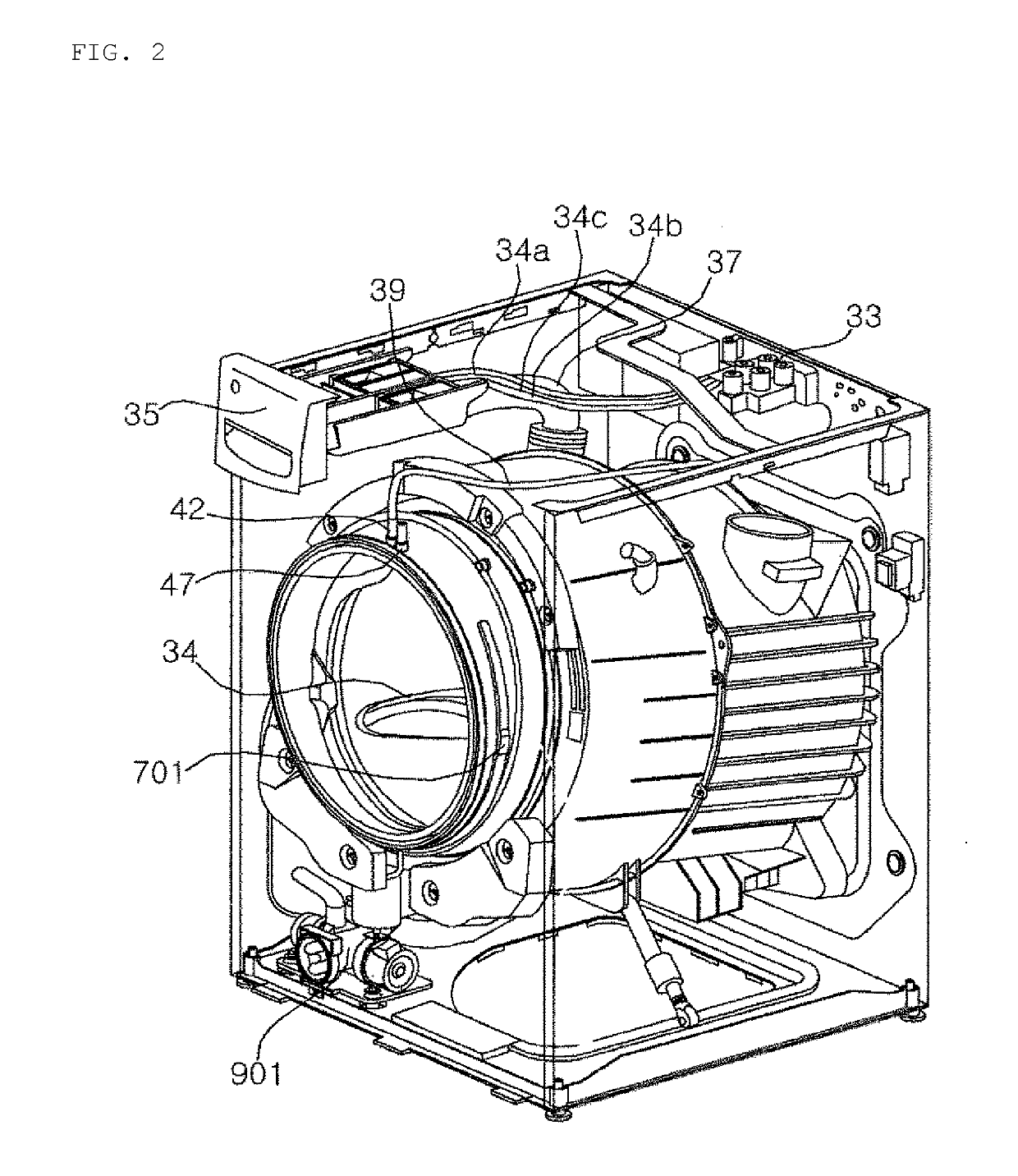
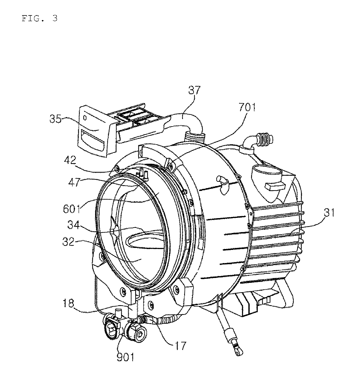
[0288]FIG. 1 is a perspective view showing a washing machine according to the present invention. FIG. 2 shows a part of the washing machine shown in FIG. 1. FIG. 3 shows a part of the washing machine shown in FIG. 2. FIG. 4 is a side sectional view of the washing machine shown in FIG. 2. FIG. 5 is a perspective view showing a pump. FIG. 6 is a cross-sectional view (a) of a circulating water chamber of the pump shown in FIG. 5, and is a cross-sectional view (b) of a drain chamber.

[0289]Referring to FIGS. 1 to 6, a casing 10 forms an outer appearance of the washing machine, and an input port 12h through which laundry is inputted is formed on the front surface thereof. The casing 10 may include a cabinet 11 that has a front surface which is opened and has a left surface, a right surface, and a rear surface, and a front panel 12 that is coupled to the opened front surface of the cabinet 11 and has the input port 12h. A bottom surface and an upper surface of the cabinet 11 are opened, an...

second embodiment

[0373]FIG. 18 is a view showing a nozzle water supply pipe provided in a washing machine according to the present invention.

[0374]Referring to FIG. 18, the nozzle water supply pipe 702 according to another embodiment of the present invention is different from the nozzle water supply pipe 702 according to the above-described embodiment only in a configuration of the uplift portions 717c and 717d and the connecting units 711′, 713, 714 and 715′ constituting the transfer conduit 71b, and the other configurations are the same. Hereinafter, the same reference numerals are assigned to the same configurations as those in the above-described embodiment, and the description thereof will be omitted herein.

[0375]In comparison with the above-described embodiment, the annular nozzle water supply pipe 702 is provided with uplift portions 717c and 717d formed in a position corresponding to the pair of lower nozzles 610c and 610d respectively, while the uplift portion is not formed in the positions...

third embodiment

[0379]FIG. 19 is a front view showing a state in which a nozzle water supply pipe is installed in a gasket in a washing machine according to the present invention. FIG. 20 is a perspective view of FIG. 19 from another angle. FIG. 21 shows a port insertion pipe shown in FIG. 19. FIG. 22 shows a nozzle water supply port shown in FIG. 19. FIG. 23 is a cross-sectional view taken at a portion where the port insertion pipe and the nozzle water supply port are coupled.

[0380]Hereinafter, the same reference numerals are assigned to the same configurations as those in the above-described embodiment, and the description thereof will be omitted herein.

[0381]The nozzle water supply pipe 703 may include a circulation pipe connection port 75, a transfer conduit 71c, and a plurality of water supply ports 72b, 72c, 72d, 72e protruded from the transfer conduit 71c.

[0382]The nozzle water supply pipe 703 branches the circulating water discharged from the circulation pipe 18 to form a first sub-flow FL...


PUM


Abstract

A washing machine includes a casing, a tub, a drum, a pump for sending water discharged from the tub, a gasket connecting an input port of the casing to an opening of the tub and having a nozzles for spraying water into the drum, and a nozzle water supply pipe fixed to the gasket configured to guide water introduced through the opening into a first sub-flow and a second sub-flow. The nozzle water pipe includes first nozzle water supply ports, formed on a first flow path to which the first sub-flow is guided, for supplying the first sub-flow to any two or more nozzles among the plurality of nozzles, and second nozzle water supply ports, formed on a second flow path to which the second sub-flow is guided, for supplying the second sub-flow to other two or more nozzles among the plurality of nozzles.

Description

TECHNICAL FIELD[0001]The present invention relates to a washing machine having a nozzle for discharging water which is discharged from a tub and circulated along a circulation pipe into a drum.BACKGROUND ART[0002]Generally, a washing machine is an apparatus that separates contaminants from clothing, bedding, and the like (hereinafter, referred to as “laundry”) by using a chemical decomposition of water and detergent and a physical action such as friction between water and laundry.[0003]Such a washing machine includes a tub containing water and a drum rotatably installed in the tub to receive the laundry. A recent washing machine is configured to circulate water discharged from the tub by using a circulation pump, and to spray the circulated water into the drum through a nozzle. However, since such a conventional washing machine usually includes a single or two nozzles, not only in the case of the single nozzle but also in the case of the two nozzles, the spraying direction is restri...

Claims


Application Information

Patent Timeline
Patent Type & Authority Applications(United States)
IPC IPC(8): D06F39/08D06F33/02D06F37/06D06F37/22D06F37/30
CPCD06F37/22D06F39/088D06F37/06D06F37/30D06F33/02D06F39/083D06F37/266D06F33/36D06F2103/04D06F2103/24D06F2105/06D06F2105/48
Inventor JUNG, HWANJINIM, MYUNGHUNLEE, JUNGHOONWOO, KYUNGCHULKIM, JAEHYUNKIM, HYUNDONG
Owner LG ELECTRONICS INC
Why Eureka
Try Eureka