

Height detection apparatus and charged particle beam apparatus
- Summary
- Abstract
- Description
- Claims
- Application Information
AI Technical Summary
Benefits of technology
Problems solved by technology
Method used
Image

Examples
first embodiment
Modification of First Embodiment
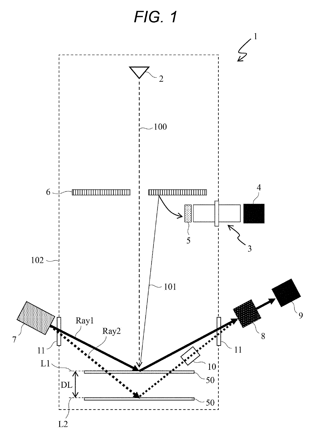
[0075]The optical height detection apparatus of the first embodiment disposes the optical path length correction member 10 having thickness designed on the basis of Formula 3 on the detection optical system 8 side with respect to the sample 50. As the optical path length correction member, it is allowable to prepare two optical path length correction members 40 each having a thickness of half the thickness dP determined by Formula (3) and then it is allowable to install the optical path length correction member 40 both on the projection optical system 7 side with respect to the sample 50 and on the detection optical system 8 side with respect to the sample 50.
[0076]FIG. 6 is a view illustrating an optical height detection apparatus according to the present modification. The optical height detection apparatus according to the present modification is different from the optical height detection apparatus according to the first embodiment in design and ar...
second embodiment
Modification of Second Embodiment
[0086]The optical height detection apparatus according to the second embodiment has a configuration in which four light beams are received by one imaging element 9. The optical height detection apparatus may emit a larger number of light beams and may use two or more imaging elements 9 to detect the height of the sample 50.
[0087]For example, the optical height detection apparatus may be configured such that the projection optical system 7 outputs six light beams, and two imaging elements 9 are prepared, and then, three of the six light beams are to be incident on each different one of the imaging elements 9. In that case, the optical path length correction member 20 that is elongated corresponding to the increase in the optical path length is disposed corresponding to each of the optical paths with reference to the short optical path among the light beams incident on the identical imaging element 9. With this configuration, the magnification of the s...
third embodiment
[0088]FIGS. 8A to 8C are views illustrating an optical height detection apparatus according to a third embodiment. Description of the same portions as those of the first embodiment or portions having the same function will be omitted. In the drawings, the same reference numerals are those having similar functions.
[0089]FIG. 8A is a view illustrating an entire optical system of the optical height detection apparatus according to the third embodiment. The third embodiment is different from the first embodiment in a method of separating a light beam into a plurality of light beams in the projection optical system 7. In the third embodiment, a half mirror 7d is used instead of the plurality of slit groups in order to separate a light beam into a plurality of light beams in a projection optical system 7′. The half mirror 7d is an optical member that partially reflects the light while transmitting the remaining light.
[0090]In FIG. 8A, a light beam to detect the height with reference to th...
PUM
 Abstract
Description
Claims
Application Information