
Image forming apparatus

a technology of image forming apparatus and forming chamber, which is applied in the direction of electrographic process, electrical apparatus casing/cabinet/drawer, instruments, etc., can solve the problems of increasing the cost and increasing the cost and size of the image forming apparatus, etc., and achieving the effect of increasing the cost and size, stabilizing the paper conveyance performan

Active Publication Date: 2019-10-24
KONICA MINOLTA INC
View PDF1 Cites 1 Cited by
  • Summary
  • Abstract
  • Description
  • Claims
  • Application Information

AI Technical Summary

Benefits of technology

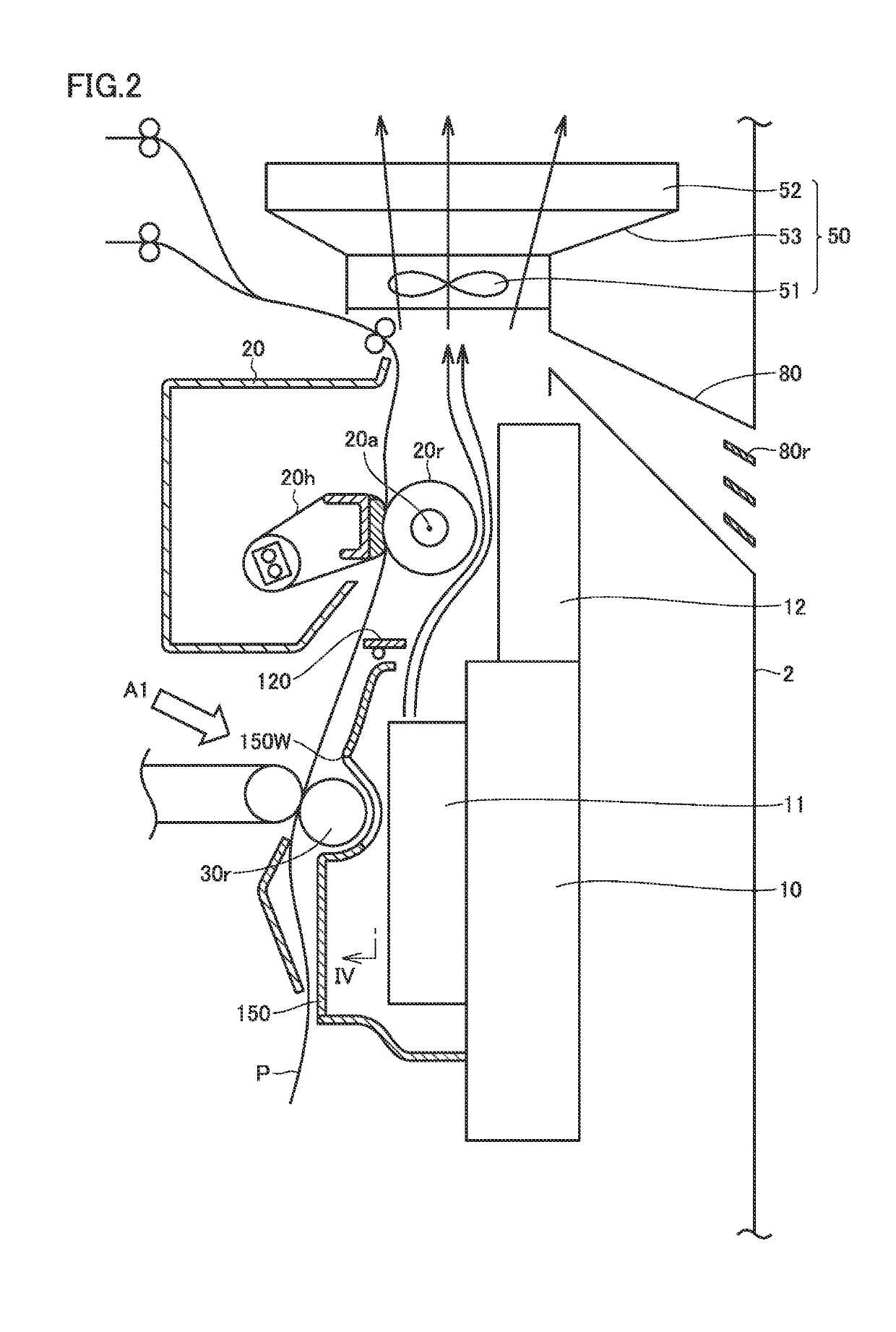
The present invention aims to solve the problem of increased cost and size of image forming apparatuses caused by the installation of additional fans. The invention proposes using air discharged from a fan for stabilizing paper conveyance performance to cool each end of a fixing roller, and then discharging it through a filter. This results in improved paper conveyance performance, an appropriate interior temperature, cooling of each end of the fixing roller, and collection of UFP while suppressing the cost and size of the image forming apparatus.

Problems solved by technology

Also, further acceleration of the speed of conveying a sheet of paper reveals problems that the stability for sheets of paper in a discharge unit of a secondary transfer roller is not kept, the heat in the fixing device rises to thereby increase the discharge amount of ultrafine particles (UFP), and the temperature inside the image forming apparatus rises.
However, additional installments of fans lead to new problems that the image forming apparatus is increased in cost and size.

Method used


Image

  • Image forming apparatus
  • Image forming apparatus
  • Image forming apparatus

Examples


Embodiment Construction

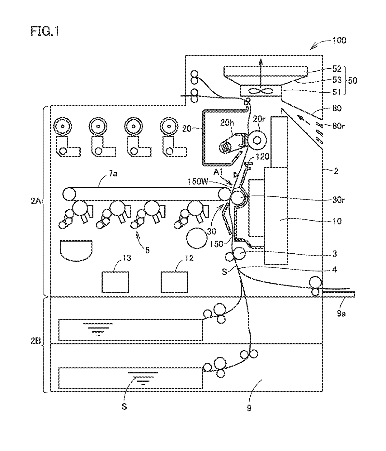
[0024]Hereinafter, one or more embodiments of the present invention will be described with reference to the drawings. However, the scope of the invention is not limited to the disclosed embodiments.

[0025]In the following, an image forming apparatus according to the present embodiment will be described with reference to the accompanying drawings. In the embodiments described below, when the number, the quantity and the like are mentioned, the scope of the present invention is not necessarily limited thereto unless otherwise specified. The same or corresponding components are designated by the same reference characters, and the description thereof may not be repeated. The drawings are not shown in accordance with the actual dimensional ratio, and there are some parts shown in different dimensional ratios for clearly illustrating the structure in order to allow easy understanding of the structure.

[0026](Image Forming Apparatus 100)

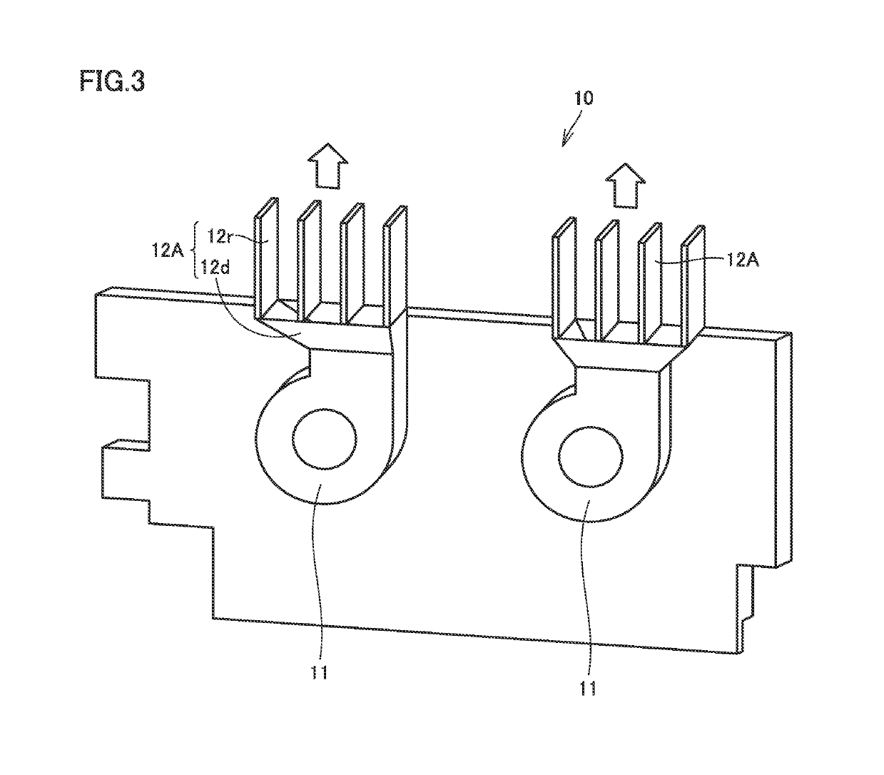
[0027]Referring to FIGS. 1 to 5, the schematic configur...


PUM


Abstract

An image forming apparatus includes: a secondary transfer roller configured to transfer a toner image onto a sheet of paper; a fixing device provided downstream in a direction in which the sheet of paper is conveyed, the fixing device including a fixing roller that is configured to fix the toner image transferred onto the sheet of paper; a paper suction fan unit configured to suction air such that air flows over the secondary transfer roller; and a guide member provided in the paper suction fan unit and configured to guide air discharged from the paper suction fan unit to be discharged toward the fixing roller. The guide member is configured to guide air in a direction crossing a rotation axis of the fixing roller at least toward each of ends of the fixing roller in a direction of the rotation axis.

Description

[0001]The entire disclosure of Japanese Patent Application No. 2018-081380, filed on Apr. 20, 2018, is incorporated herein by reference in its entirety.BACKGROUNDTechnological Field[0002]The present invention relates to an image forming apparatus such as a copier, a laser beam printer, a facsimile machine, and a multi-functional peripheral thereof.Description of the Related Art[0003]An image forming apparatus applies heat to a toner image using a fixing device in order to fix the toner image onto a sheet of paper. A fixing roller provided inside the fixing device has a region over which a sheet of paper passes and to which heat is transferred, so that the temperature of this region lowers. This requires continuous application of heat while a sheet of paper is fed. As a result, the temperature tends to rise at each end of the fixing roller over which no sheet of paper passes.[0004]Also, further acceleration of the speed of conveying a sheet of paper reveals problems that the stabilit...

Claims


Application Information

Patent Timeline
IPC IPC(8): G03G15/20G03G21/20B65H5/06
CPCB65H5/068G03G21/206G03G15/2017G03G21/20H05K5/0213G03G2215/2038G03G15/161
Inventor NARUSE, KUNIHIKO
Owner KONICA MINOLTA INC
Learn More