In-situ sensor

a sensor and in-situ technology, applied in the field of therapies, can solve the problems of difficult tracking of long-term effects and/or efficacy of therapies, affecting surrounding tissue, and encompassing side effects

Active Publication Date: 2019-10-31
TECHN UNIV HAMBURG HARBURG +1
View PDF0 Cites 4 Cited by
  • Summary
  • Abstract
  • Description
  • Claims
  • Application Information

AI Technical Summary

Benefits of technology

[0009]To overcome one or more problems in the art, the invention proposes an in-situ sensor which is able to monitor various effects occurring during treatment.

Problems solved by technology

However, some of these therapies are not easy to track with respect to their long-term effect and / or their efficacy.
These therapies in addition to their intended effect do also encompass side-effects, e.g. they also impair surrounding tissue as well as distant cells.
However, efficacy thereof is to some extent unpredictable.
Even when a cancerous tissue has been successfully treated, there is still an increased probability that one or more cancerous cell survived which may lead to a relapse.
In addition some cancerous tissue growth, such as prostate cancer, is kept under active surveillance as the impact of surgery and / or therapy is sometimes held inappropriate in comparison to an expected life time of a patient.
However, such surveillance is often expensive and time-consuming.
In addition detecting of some of this tissue (and its growth / shrinkage to due therapy) is rather complicated as some of the tissue growth may not be visualized by today's imaging technologies.

Method used


Image

  • In-situ sensor
  • In-situ sensor
  • In-situ sensor

Examples


Embodiment Construction

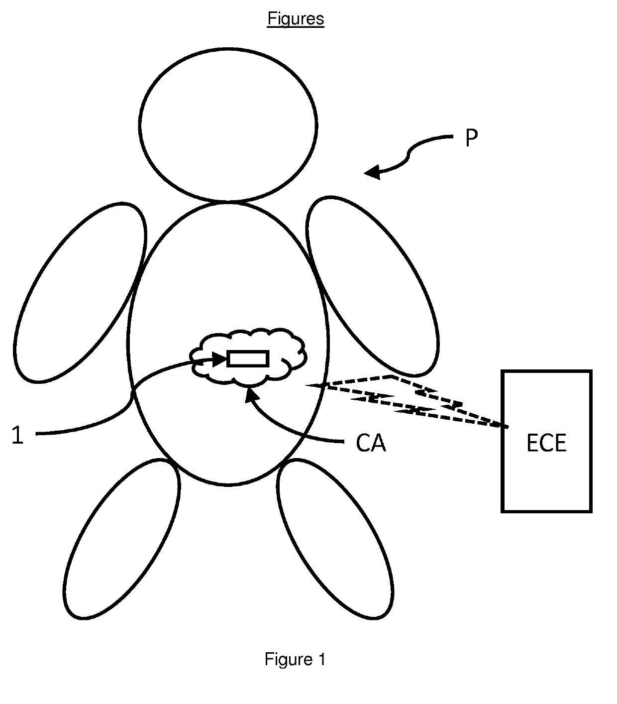
[0016]The present disclosure describes preferred embodiments with reference to the Figures, in which like reference signs represent the same or similar elements. Reference throughout this specification to “one embodiment,”“an embodiment,” or similar language means that a particular feature, structure, or characteristic described in connection with the embodiment is included in at least one embodiment of the present invention. Thus, appearances of the phrases “in one embodiment,”“in an embodiment,” and similar language throughout this specification may, but do not necessarily, all refer to the same embodiment.

[0017]The described features, structures, method steps or characteristics of the invention may be combined in any suitable manner in one or more embodiments. In the description, numerous specific details are recited to provide a thorough understanding of embodiments of the invention.

[0018]I.e., unless indicated as alternative only any feature of an embodiment may also be utilize...


PUM


Abstract

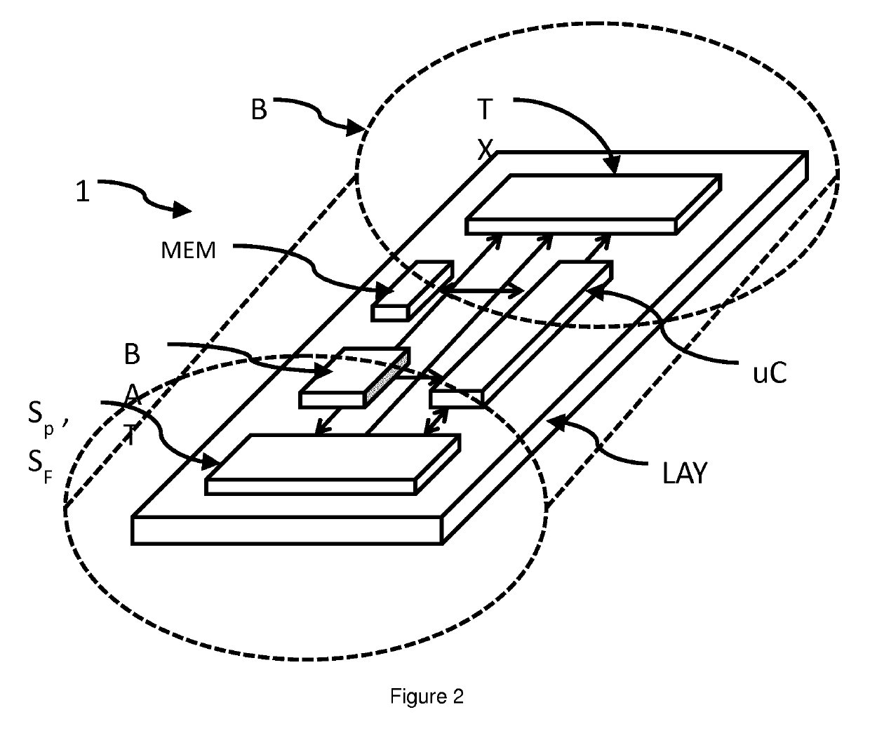
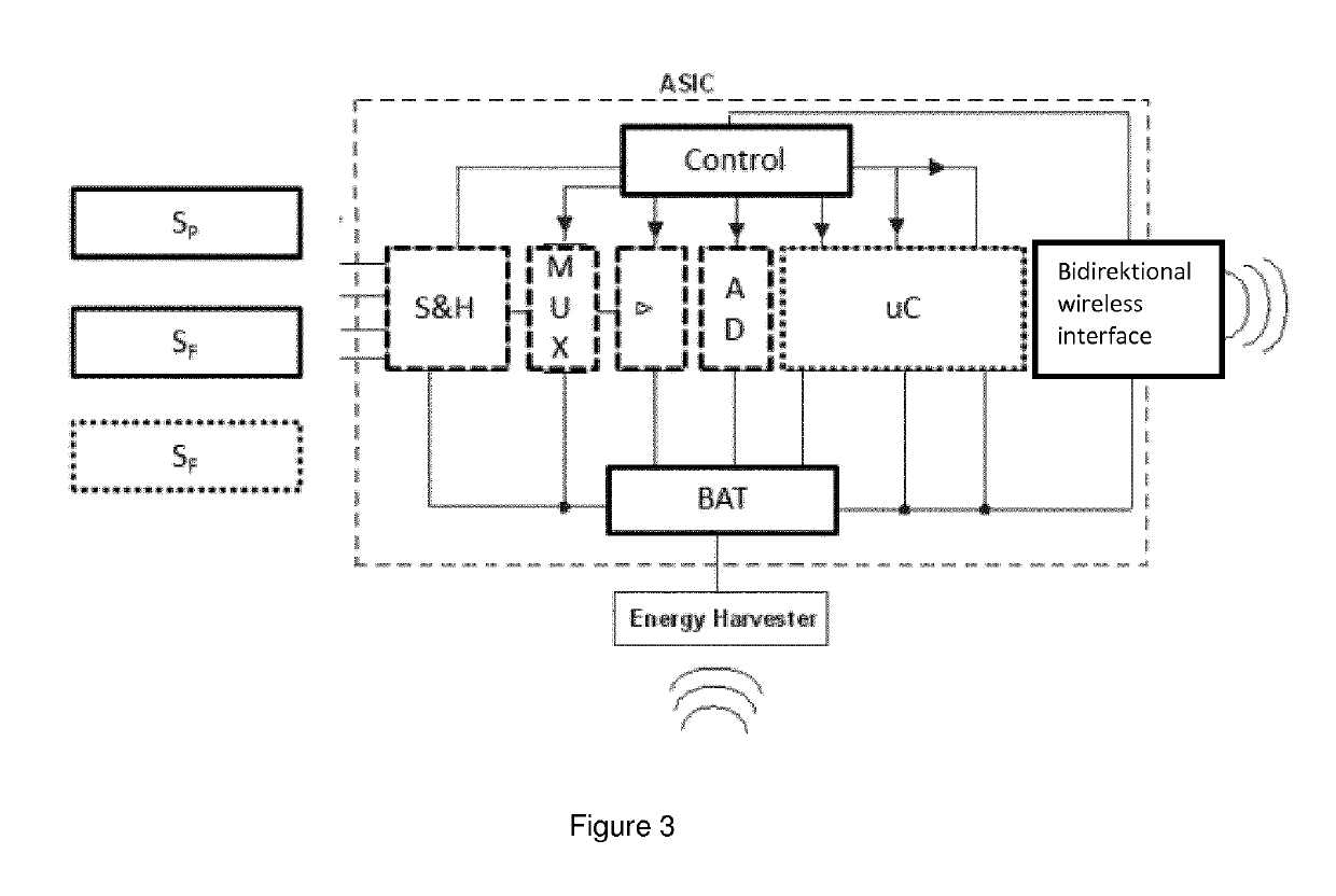
The invention proposes an In-situ Sensor (1) for being implanted within tissue of a mammal (P) comprising •an energy harvesting portion (RX), •a communication portion (TX), •a pressure sensor (SP) for measuring interstitial pressure of surrounding tissue when located within tissue, •a further sensor (SF), whereby the further sensor is selected from a group comprising pH sensor, lactate sensor, impedance sensor, radiation sensor, temperature sensor, sensor for bioelectrical potentials, •whereby said further sensor (SF), said pressure sensor (SP) as well as the communication portion (TX) are powered by the energy harvesting portion (RX), •whereby information indicative of the measurement provided by the pressure sensor (SP) and data indicative of the measurement provided by said further sensor (SF) is communicated via said communication portion (TX) towards an extracorporeal receiving entity (ECE), •whereby said communication portion (TX) and/or said pressure sensor (SP) and/or said further sensor (SF) are adaptable such that they consume less energy in case storage of energy by the energy harvesting portion (RX) drops below a certain threshold.

Description

BACKGROUND[0001]Within the medical field numerous therapies are available. However, some of these therapies are not easy to track with respect to their long-term effect and / or their efficacy. In the following we will describe such conditions with respect to benign or malign tissue. However, the invention is not limited thereto.[0002]Treatment of malign tissue more often referred to as cancer treatment often involves some sort of radiation therapy and / or chemo therapy. Some of these therapies may be focused towards the target area while others are less selective.[0003]These therapies in addition to their intended effect do also encompass side-effects, e.g. they also impair surrounding tissue as well as distant cells.[0004]However, efficacy thereof is to some extent unpredictable. When trying to define a dosage regime, it is often a trade-off between minimizing side-effects while still providing a desired effect.[0005]Even when a cancerous tissue has been successfully treated, there i...

Claims


Application Information

Patent Timeline
Patent Type & Authority Applications(United States)
IPC IPC(8): A61B5/00A61B5/03H03M1/12H04B1/02
CPCA61B5/036A61B5/686H03M1/12A61B5/0031A61B2562/0271A61B5/0015A61B2560/0219A61B2562/17H04B1/02A61B2562/0247A61B2562/16
Inventor SCHUMACHER, UDOKRAUTSCHNEIDER, WOLFGANGSCHRODER, DIETMAR
Owner TECHN UNIV HAMBURG HARBURG
Why Eureka
Try Eureka