Vehicle suspension system

a suspension system and vehicle technology, applied in the field of vehicle suspension systems, can solve the problems of high manufacturing cost, high complexity, and high cost of vehicle mass, and achieve the effect of easy and secure track width chang

Active Publication Date: 2019-10-31
TRIGGO SA
View PDF21 Cites 3 Cited by
  • Summary
  • Abstract
  • Description
  • Claims
  • Application Information

AI Technical Summary

Benefits of technology

[0004]Certain embodiments of the invention provide an alternative suspension system for a vehicle with variable track width, which allows for easy and secure track-width change, utilizing cost effective means. In particular, the invention provides a suspension that allows the wheel to maintain a selected orientation with respect to the vehicle chassis during changing of the track width. The invention further provides a suspension that allows adjustment of toe angle while the suspension transitions from between the retracted and extended configuration. The invention also provides means for counter-acting changes of effective wheel suspension load resulting from the changes in load distribution, which in turn is caused by wheelbase dimension changes between the retracted and extended configuration.

Problems solved by technology

The disadvantage of these vehicles is that a change in track width is effected using dedicated, costly hydraulic or electrical means.
This results in higher mass of the vehicle, higher manufacturing costs and higher complexity.

Method used


Image

  • Vehicle suspension system
  • Vehicle suspension system
  • Vehicle suspension system

Examples


first embodiment

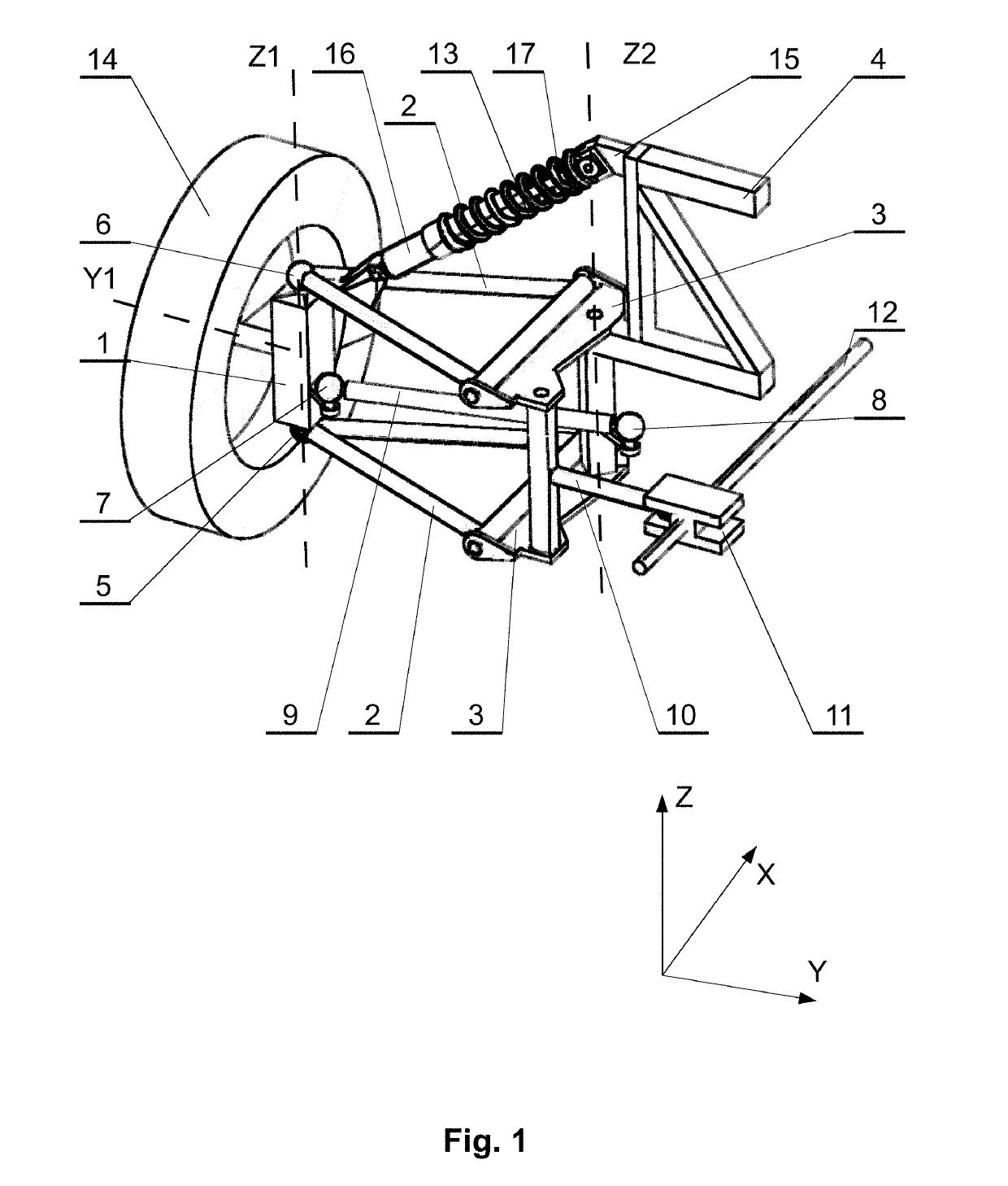
[0030]In some embodiments both vertical and horizontal position of the connection point 15 may be moveable and controlled by dedicated control means in order to achieve proper positioning of the steering knuckle 1 and a wheel 14 versus chassis of the vehicle, and / or to control the load drawn on the spring element of the shock absorber 13. Such vertical and / or horizontal position control can be achieved for example via appropriate control means acting on a pivotable arm 18, as shown in FIG. 4 in relation to the first embodiment, and in relation to further embodiments.

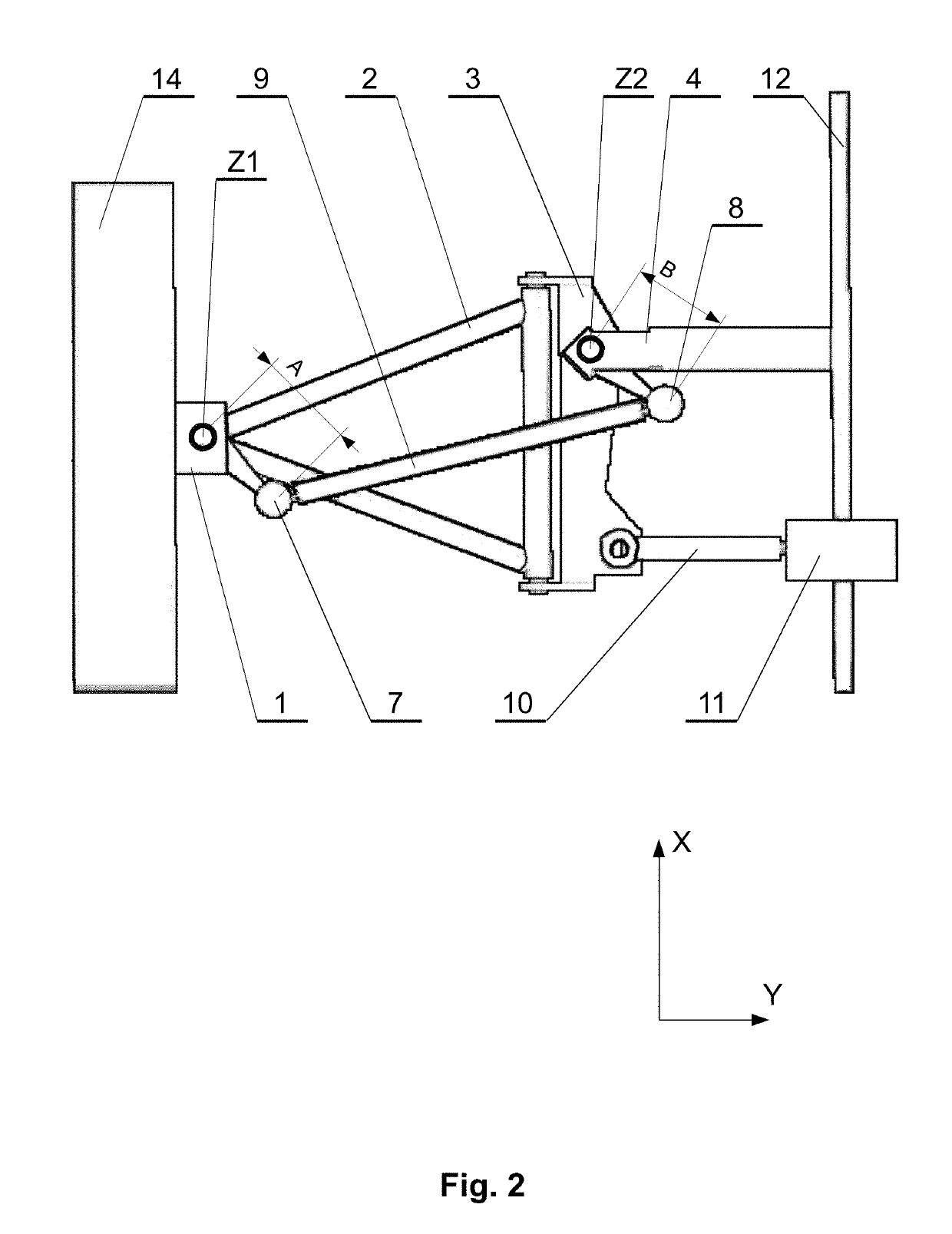
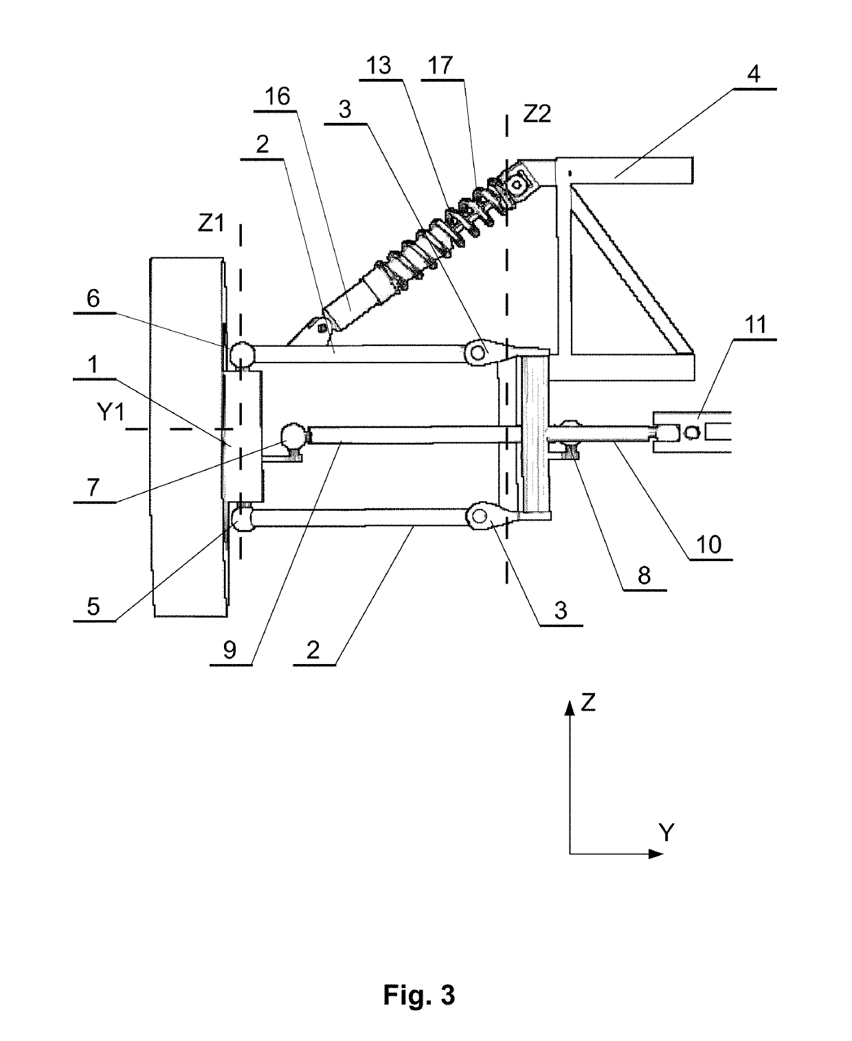
[0031]FIG. 2 shows a vehicle suspension system according to the first embodiment in a top view, while FIG. 3 shows the vehicle suspension system according to the first embodiment in a side view. The steering knuckle 1 is connected in a second connection point 7 by a second ball joint with the rigid member 9. The steering knuckle 1 is enabled to rotate around an axis Z1. Preferably, the axis Z1 is parallel to vertical veh...

third embodiment

[0042]FIG. 9 shows a vehicle suspension system in an isometric view. In this embodiment, the suspension utilizes one control arm 2 (a wishbone) and rods 24 located substantially parallel with respect to the wishbone. Such multi-link suspension is light weight and easier to manufacture. It allows to obtain an independent scrub radius of a desired value and a significant pitch compensation during braking and accelerating. Forces originating from wheels may be transferred to the body, while maintaining a large distance between the fixing points. It is also possible to obtain a preferred toe angle and camber angle, depending on deflection of the suspension.

[0043]It should be borne in mind that any of the embodiments shown in FIGS. 7-9 can be also carried out without the moving arm 18 and the movable connection point 15, i.e. analogously to the first embodiment, with a fixed connection point 15.


PUM


Abstract

A suspension system for a vehicle. The suspension system has a steering knuckle connected through suspension means with a vehicle chassis portion, guiding means and driving means. The guiding means enable movement of the steering knuckle with respect to the vehicle chassis portion along an arched pathway between a first and a second position. The driving means effect the movement of the steering knuckle between the first and the second position. The guiding means effect a selected angular orientation of the steering knuckle with respect to the vehicle chassis portion during the movement between the first position and the second position.

Description

TECHNICAL FIELD[0001]The invention relates to vehicles with variable track.BACKGROUND[0002]Variable track axles are used to enhance the functionality of vehicles, by facilitating the use of vehicles in different environments, adjustment of vehicle aerodynamics at different speeds or adjustment of vehicle stability at different driving conditions.[0003]The disadvantage of these vehicles is that a change in track width is effected using dedicated, costly hydraulic or electrical means. This results in higher mass of the vehicle, higher manufacturing costs and higher complexity.SUMMARY OF THE INVENTION[0004]Certain embodiments of the invention provide an alternative suspension system for a vehicle with variable track width, which allows for easy and secure track-width change, utilizing cost effective means. In particular, the invention provides a suspension that allows the wheel to maintain a selected orientation with respect to the vehicle chassis during changing of the track width. Th...

Claims


Application Information

Patent Timeline
Patent Type & Authority Applications(United States)
IPC IPC(8): B60G17/00B60G7/00B62D7/18B60G3/20
CPCB60G3/20B60G17/00B62D7/18B60G7/001B60G2200/18B60G2500/40B60G2200/144B60G2300/40F16H25/20B60G2206/50B60Y2400/412
Inventor BUDWEIL, RAFAL
Owner TRIGGO SA
Why Eureka
Try Eureka