
Battery management system

a battery management system and battery technology, applied in secondary cell servicing/maintenance, cell components, instruments, etc., can solve the problems of reducing the capacity and cycle life deteriorating measurement accuracy, and error in the measurement of the actual cell voltage, so as to improve the actual cell voltage measurement accuracy, improve the efficiency of the battery pack, and accurately monitor and control the condition of the battery pack

Active Publication Date: 2019-10-31
SAMSUNG SDI CO LTD
View PDF0 Cites 1 Cited by
  • Summary
  • Abstract
  • Description
  • Claims
  • Application Information

AI Technical Summary

Benefits of technology

The patent describes a way to improve the accuracy of measuring the voltage of individual battery cells in a battery pack. This is done by measuring the resistance of the bus bars that connect the cells, and then using these measurements to correct the voltage of each cell. By doing this, we can accurately monitor and control the condition of the battery pack, which can increase efficiency and improve the battery's lifespan.

Problems solved by technology

However, the impedance of the bus bar causes a voltage drop due to a battery current, so that an error may occur in a measured voltage value of the battery cell due to the impedance.
Such a voltage measurement error for each battery cell is not large, but voltage measurement errors are accumulated in a battery pack management system that manages several tens to hundreds of battery cells, which deteriorates the measurement accuracy.
Therefore, an error occurs between a calculated SOC value and an actual SOC value for a balancing operation between battery cells or a charging / discharging operation of the battery cells, thereby reducing the capacity and cycle-life of a battery pack.

Method used


Image

  • Battery management system
  • Battery management system
  • Battery management system

Examples


Embodiment Construction

[0015]In the following detailed description, only certain exemplary embodiments of the present invention have been shown and described, simply by way of illustration. As those skilled in the art would realize, the described embodiments may be modified in various different ways, all without departing from the spirit or scope of the present invention. Accordingly, the drawings and description are to be regarded as illustrative in nature and not restrictive. Like reference numerals designate like elements throughout the specification.

[0016]Throughout this specification and the claims that follow, when it is described that an element is “coupled / connected” to another element, the element may be “directly coupled / connected” to the other element or “indirectly coupled / connected” to the other element through a third element. In addition, unless explicitly described to the contrary, the word “comprise” and variations such as “comprises” or “comprising” will be understood to imply the inclus...


PUM

PropertyMeasurementUnit
resistanceaaaaaaaaaa
voltage measuringaaaaaaaaaa

Abstract

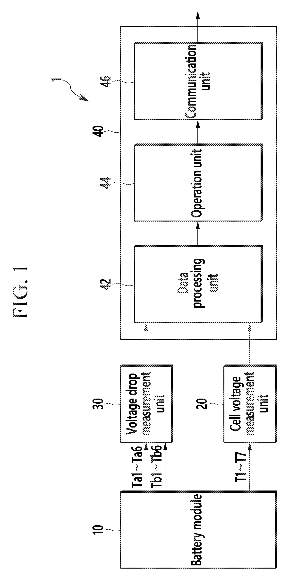
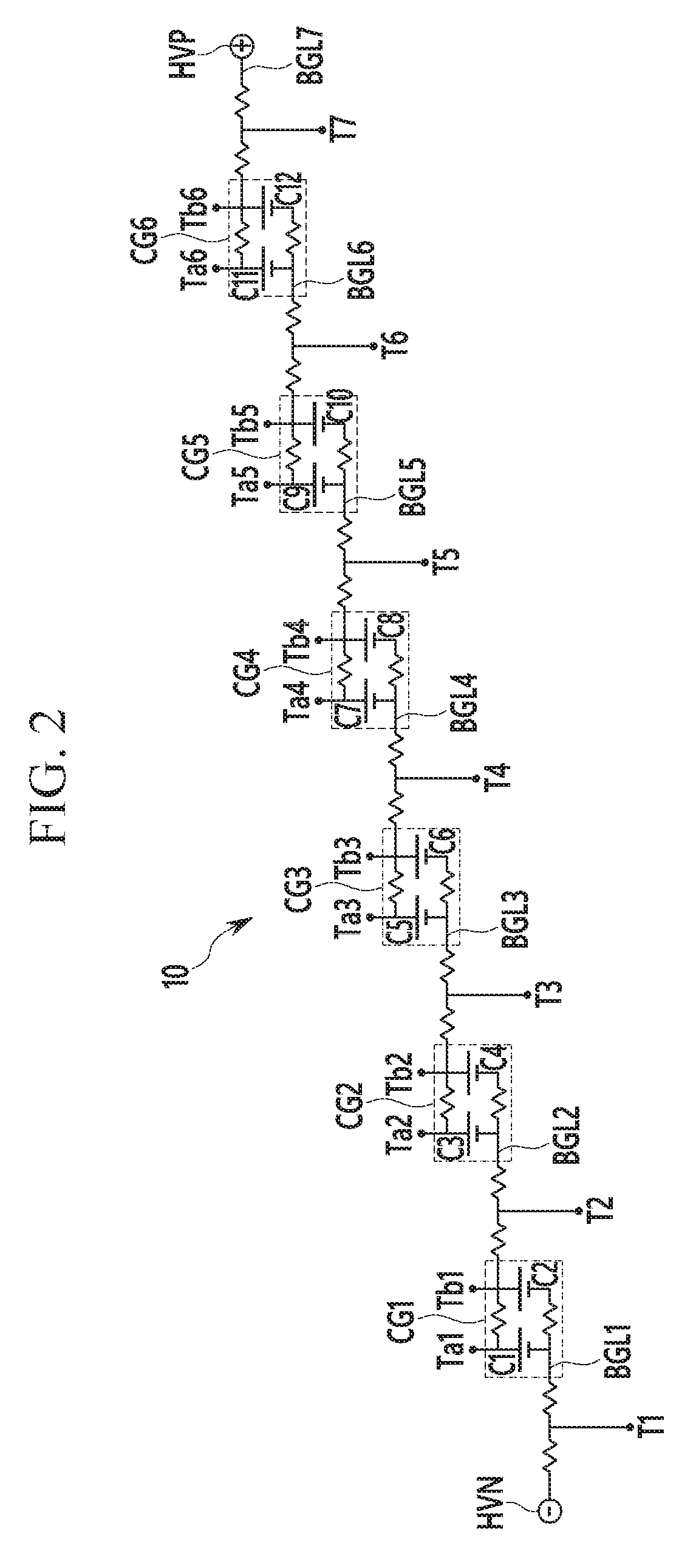
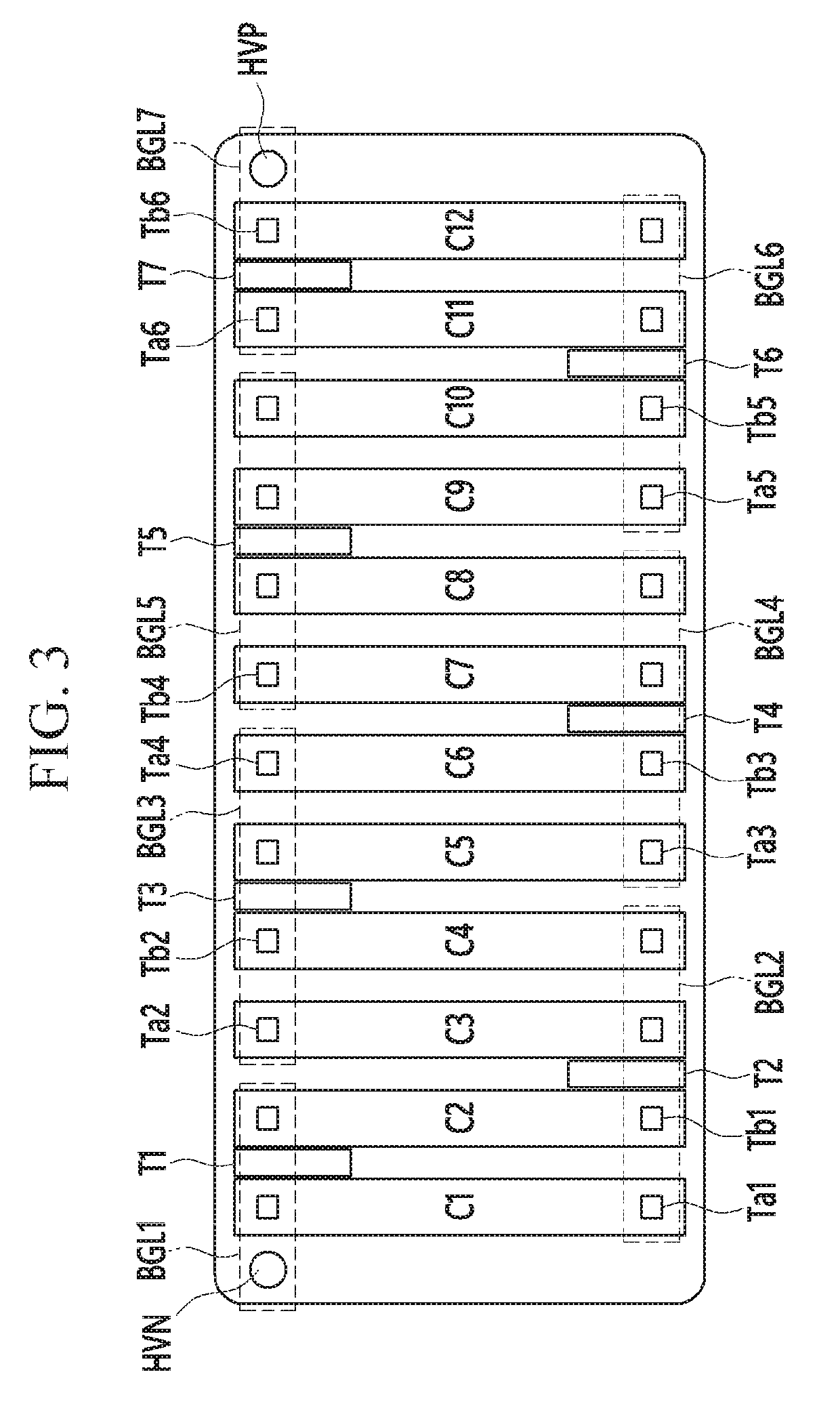
The present invention relates to a battery management system, which includes: at least one cell group configured to include first and second battery cells connected in parallel between first and second bus bars; a plurality of first and second measurement terminals positioned on the first and second bus bars;a plurality of third and fourth measurement terminals positioned at positions on the first bus bar, which correspond to one of ends of each of the first and second battery cells, respectively; a cell voltage measuring unit configured to measure a cell voltage of the cell group by using the first and second measurement terminals; a voltage drop measuring unit configured to measure an error voltage corresponding to a resistance value of the first bus bar by using the third and fourth measurement terminals; and a battery management unit configured to calculate a corrected cell voltage by using the cell voltage and the error voltage.

Description

TECHNICAL FIELD[0001]The present invention relates to a battery management system.BACKGROUND ART[0002]In a battery management system, impedance of a bus bar connecting battery cells is very low. However, the impedance of the bus bar causes a voltage drop due to a battery current, so that an error may occur in a measured voltage value of the battery cell due to the impedance.[0003]Such a voltage measurement error for each battery cell is not large, but voltage measurement errors are accumulated in a battery pack management system that manages several tens to hundreds of battery cells, which deteriorates the measurement accuracy. Therefore, an error occurs between a calculated SOC value and an actual SOC value for a balancing operation between battery cells or a charging / discharging operation of the battery cells, thereby reducing the capacity and cycle-life of a battery pack.[0004]The above information disclosed in this Background section is only for enhancement of understanding of t...

Claims


Application Information

Patent Timeline
Patent Type & Authority Applications(United States)
IPC IPC(8): G01R31/3835H02J7/00G01R31/388H01M10/42H01M10/48H01M2/20H01M50/204H01M50/505H01M50/509H01M50/512H01M50/569
CPCH01M10/482H01M10/425H01M2/206H02J2007/0067G01R31/388H02J7/0063G01R31/3835H01M2010/4271Y02E60/10H01M50/204H01M50/509H01M50/512H01M50/505H01M50/569H01M10/48H01M10/42G01R31/364G01R31/396G01R31/374G01R31/3648G01R31/389H02J7/0025
Inventor JEON, YOONSUKJUNG, GOOYUN
Owner SAMSUNG SDI CO LTD
Learn More