Electric motor

a technology of electric motors and motors, applied in the direction of braking components, magnetic circuit shapes/forms/constructions, braking systems, etc., can solve the problems of increasing operating noise or load on the support portion, reducing density, and no useful purpose, so as to prevent dielectric breakdown, increase the space for each wiring structure, and reduce the effect of nois

Inactive Publication Date: 2019-10-31
NTN CORP
View PDF0 Cites 2 Cited by
  • Summary
  • Abstract
  • Description
  • Claims
  • Application Information

AI Technical Summary

Benefits of technology

[0025]As described above, the coils associated with the respective systems are arranged so as to be distributed in the circumferential direction, so that the wires of the coils would be complicated, and thus a space for each wiring structure would be increased. In addition, for example, when the coils in a certain electric power system have caused an abnormality due to breaking or the like during high-speed rotation using flux weakening control or the like, a very large induced voltage would be generated in the broken coil. In order to prevent dielectric breakdown due to such a large induced voltage, a sufficient creepage distance can be ensured between the wires associated with the respective systems.
[0026]According to this configuration, since the part of the wiring structure associated with the first system is extended at the radially outer portion of the stator, and the part of the wiring structure associated with the second system is extended at the radially inner portion of the stator, a necessary and sufficient creepage distance can be ensured between the wiring structure associated with the first system and the wiring structure associated with the second system. Therefore, dielectric breakdown due to generation of a very large induced voltage in a coil can be prevented. In addition, since the wiring structures associated with the respective systems are extended as described above, the wires associated with these systems do not cross each other, and thus the wiring structures can be simplified.

Problems solved by technology

However, when an abnormality has occurred in one or some of the plurality of electric power systems in such a motor, an electromagnetic force in a direction other than the rotation direction may be generated due to an imbalance in excitation magnetic flux, which may increase operating noise or load on a support portion such as a bearing.
In the case where a plurality of coils of the same phase connected to different electric power systems are adjacent to each other, as in Patent Document 2, electromagnetic forces in the rotation direction induced by currents in a space between the coils of the same phase are cancelled out, and thus the space serves no useful purpose.
Thus, the torque density decreases, which increases the size and cost of the motor.
In the case where the set of coils associated with the first system and the set of coils associated with the second system, in which the coils in each set are arranged in the same predetermined phase order, are alternately arranged as in Patent Document 3, the above imbalance in electromagnetic force easily occurs particularly in a motor having a small number of poles and a small number of slots.
Thus, with the technique of Patent Document 3, electromagnetic force can be imbalanced.

Method used


Image

  • Electric motor
  • Electric motor
  • Electric motor

Examples


first embodiment

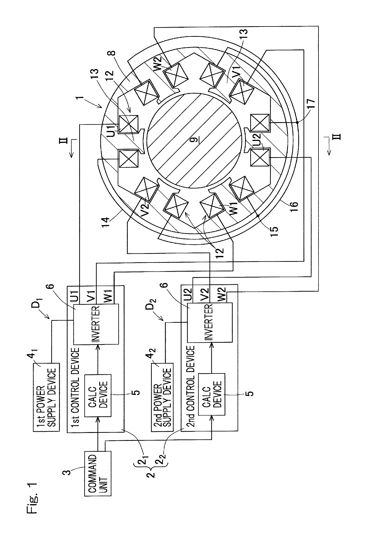
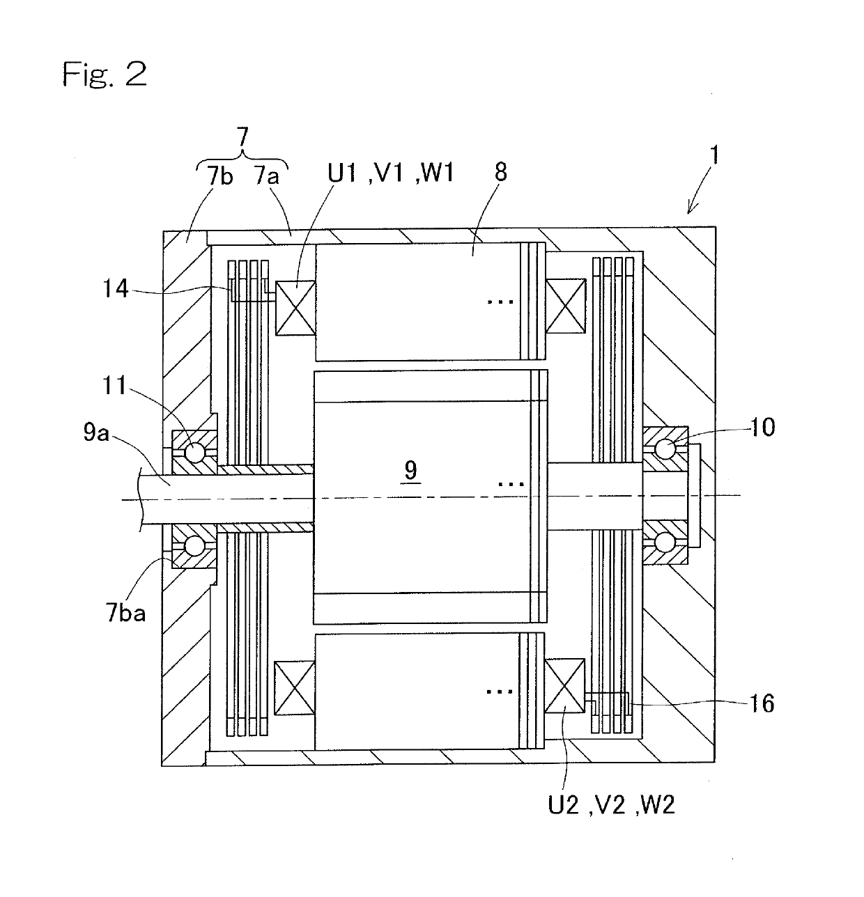
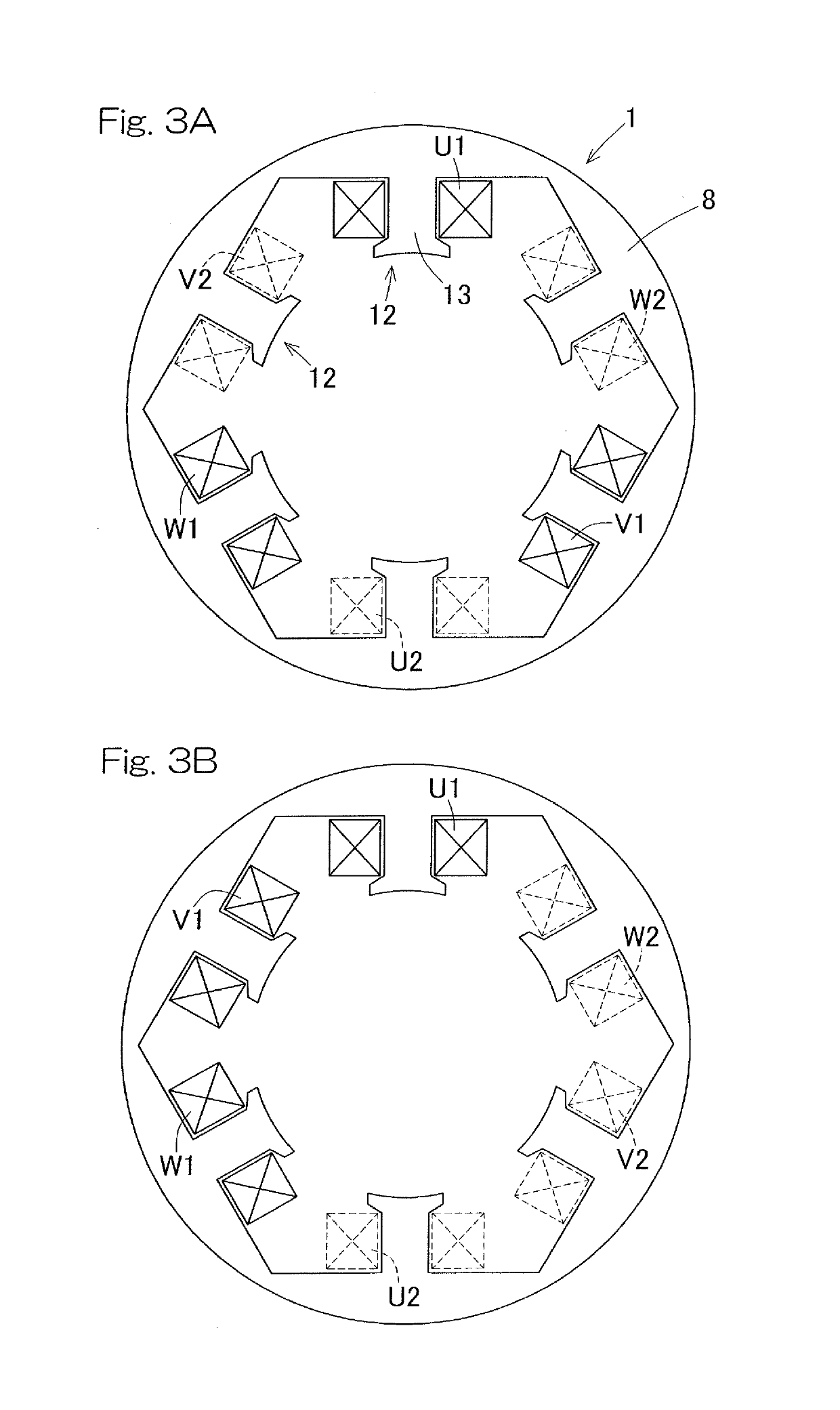
[0039]An electric motor device according to the present invention will be described with reference to FIG. 1 to FIGS. 3A and 3B. The electric motor device according to this embodiment may be used for an electric brake apparatus in a vehicle, or the like.

[0040]

[0041]FIG. 1 shows a schematic configuration of the electric motor device including redundant first and second groups (first and second system). The electric motor device includes an electric motor 1, a control device 2, and a command unit 3. The electric motor 1 has coils U1, V1, and W1 of three phases belonging to the first group (associated with the first system) and coils U2, V2, and W2 of three phases belonging to the second group (associated with the second system). The control device 2 has first and second control devices 21 and 22.

[0042]A first power supply device 41 is connected to the coils U1, V1, and W1 of the first group via the first control device 21. The first power supply device 41 and wires that connect the fi...

third embodiment

[0073]FIG. 5 shows an electric motor device and this electric motor device has an electric motor 1B. In this electric motor device, the redundant configuration in FIG. 1 is applied to the slot configuration in FIG. 4, that is, excitation magnetic poles 12 on a total of nine slots. The electric motor 1B includes three slots for each phase with respect to three-phase (U phase, V phase, and W phase) currents. The nine slots are configured such that the coils are arranged in the order of the coil U1, the coil V2, the coil W1, the coil U2, the coil V1, the coil W2, the coil U1, the coil V2, and the coil W1 along the circumferential direction in the counterclockwise direction, as shown in FIG. 5. In this case as well, the same advantageous effects as those of the above-described embodiments are achieved.

[0074]In any of the first to third embodiments, for example, in the case where redundancy of calculation devices or power supply devices is not required, an integrated single calculation ...


PUM


Abstract

Provided is an electric motor in which an imbalance in electromagnetic force is inhibited even when an abnormality has occurred in an electric power system. The motor (1) is connectable to a plurality of electric power systems (D1, D2) and includes: a stator (8) including a plurality of excitation magnetic poles (12) disposed in a circumferential direction and coils (U1, V1, W1 (U2, V2, W2)) provided on the respective poles (12), the coils including, for each of the systems (D1, D2), a set of three or more phase coils, the coils carrying respective currents of three or more phases of the corresponding system (D1, D2); and a rotor (9) rotatable relative to the stator (8). The coils (U1, V1, W1, U2, V2, W2) of the stator (8) are arranged such that coils adjacent to each other in the circumferential direction are different in phase and associated with different systems.

Description

CROSS REFERENCE TO THE RELATED APPLICATION[0001]This application is a continuation application, under 35 U.S.C. § 111(a), of international application No. PCT / JP2018 / 000525, filed Jan. 11, 2018, which claims Convention priority to Japanese patent application No. 2017-005734, filed Jan. 17, 2017, the entire disclosure of which is herein incorporated by reference as a part of this application.BACKGROUND OF THE INVENTIONField of the Invention[0002]The present invention relates to an electric motor and specifically relates to an electric motor with enhanced redundancy.Description of Related Art[0003]Regarding an electric motor, the following techniques have been proposed.[0004](1) An electric brake apparatus in which an electric motor is coaxially disposed on the outer circumference of a linear motion member (Patent Document 1).[0005](2) A radial gap motor in which windings associated with two systems are arranged such that the windings of the same phase are adjacent to each other (Pate...

Claims


Application Information

Patent Timeline
Patent Type & Authority Applications(United States)
IPC IPC(8): H02K3/28H02K1/14H02K3/20
CPCF16D2121/24H02K2213/06H02K1/146H02K3/20B60T13/74B60T2270/413H02K3/28H02K16/04
Inventor MASUDA, YUI
Owner NTN CORP
Why Eureka
Try Eureka