Supercharge Your Innovation With Domain-Expert AI Agents!

Transmission device, reception device, cable, transmission method, and reception method

Active Publication Date: 2019-10-31
PANASONIC INTELLECTUAL PROPERTY MANAGEMENT CO LTD
View PDF2 Cites 5 Cited by
  • Summary
  • Abstract
  • Description
  • Claims
  • Application Information

AI Technical Summary

Benefits of technology

The patent allows for transmitting video signals with a large amount of information.

Problems solved by technology

For this reason, physical limitations sometimes make it difficult to transmit a video signal represented by an electrical signal.

Method used


Image

  • Transmission device, reception device, cable, transmission method, and reception method
  • Transmission device, reception device, cable, transmission method, and reception method
  • Transmission device, reception device, cable, transmission method, and reception method

Examples


first exemplary embodiment

[1-1. Outline Configuration of Transmission-and-Reception System]

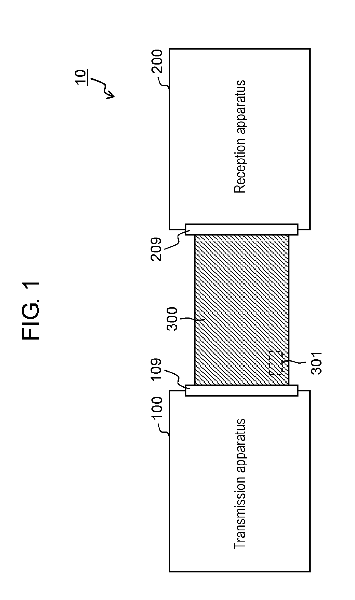
[0021]Transmission-and-reception system 10 according to a first exemplary embodiment will be described below with reference to the accompanying drawings. An outline configuration of the transmission-and-reception system 10 according to the first exemplary embodiment will be described first.

[0022]FIG. 1 is a view schematically showing the outline configuration of transmission-and-reception system 10 according to the first exemplary embodiment.

[0023]As shown in FIG. 1, transmission-and-reception system 10 includes transmission apparatus 100, reception apparatus 200, and cable 300.

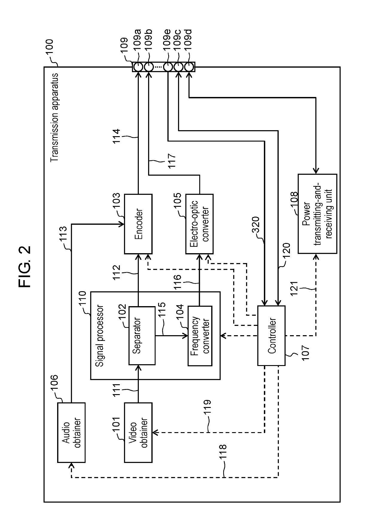
[0024]Transmission apparatus 100 is an apparatus that processes a video baseband signal and transmits the processed signal to reception apparatus 200 provided outside transmission apparatus 100. Transmission apparatus 100 operates as a source device complying with an HDMI (registered trademark) standard and includes composite connector 109. Tran...

second exemplary embodiment

[0111][2-1-1. Operation Example 1 of Second Exemplary Embodiment]

[0112]A second exemplary embodiment will exemplify a specific operation of transmission apparatus 100 described in the first exemplary embodiment. Operation example 1 will be described first.

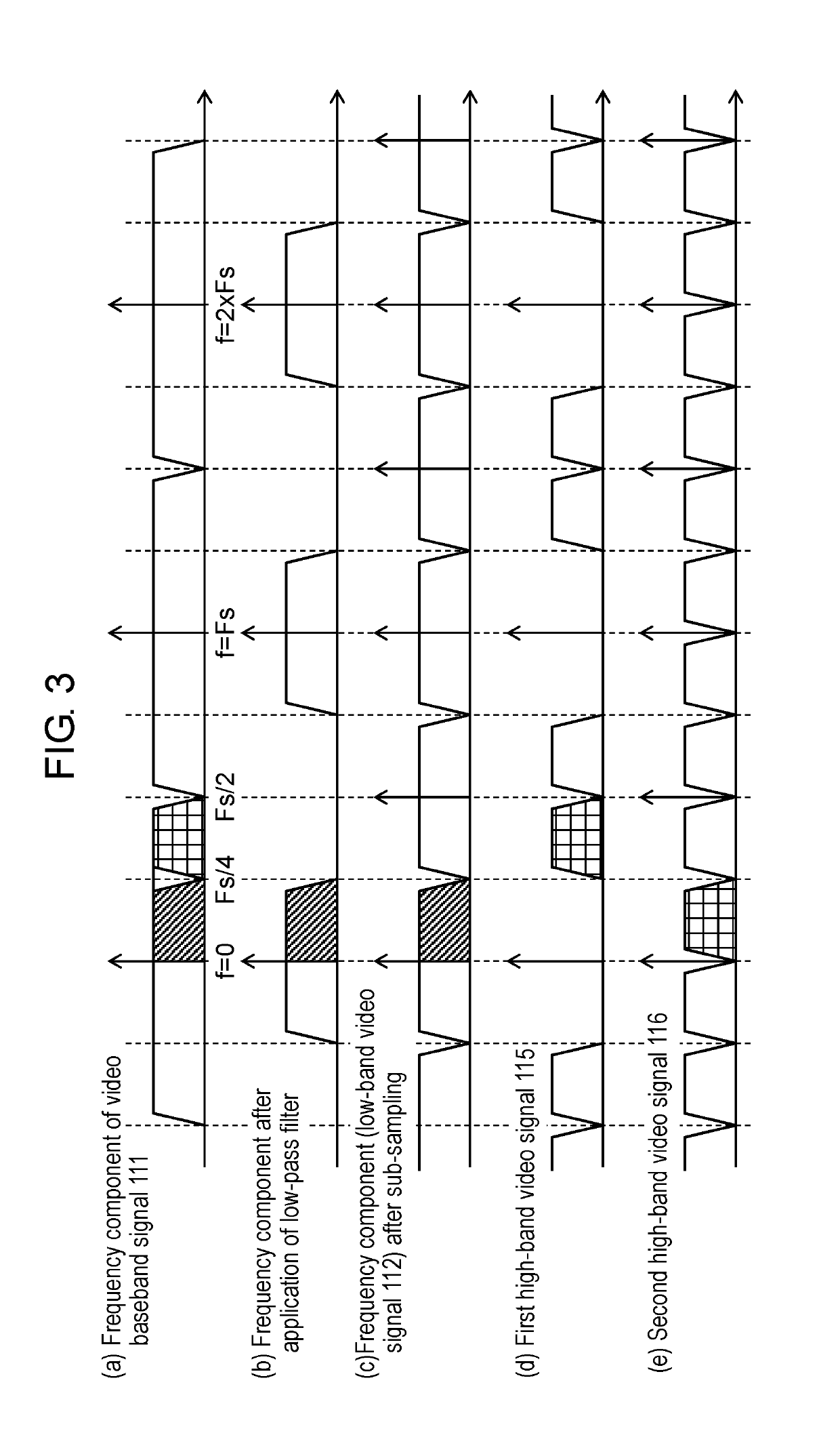
[0113]In operation example 1, separator 102 of transmission apparatus 100 separates video baseband signal 111 into low-band video signal 112 for forming an image with a fixed resolution (to be also referred to as a “predetermined resolution” hereinafter) and first high-band video signal 115 for forming an image component (high-frequency component), of the image, which has a resolution higher than the fixed resolution. The fixed resolution is, for example, a 2K resolution. More specifically, the 2K resolution is 1920×1080 / 60p (a moving image that displays 60 images with 1920 pixels×1080 pixels per sec). In this case, low-band video signal 112 is a full high vision signal of 1080p / 60 Hz (a moving image signal that displays 60 images ...

third exemplary embodiment

[3-1. Operation Example of Third Exemplary Embodiment]

[0163]A third exemplary embodiment will exemplify an operation of transmission apparatus 100 described in the first exemplary embodiment, which is different from the operation example in the second exemplary embodiment. In transmission apparatus 100, signal processor 110 may convert entire video baseband signal 111 into optical signal 117 by using electro-optic converter 105. The third exemplary embodiment will exemplify an operation in such a case.

[0164]FIG. 7 is a flowchart showing an operation example of transmission apparatus100 according to the third exemplary embodiment.

[0165]In transmission apparatus 100, video obtainer 101 obtains video baseband signal 111 for forming an image (step S31).

[0166]Signal processor 110 converts entire video baseband signal 111 obtained in step S31 into optical signal 117 by using electro-optic converter 105 (step S32).

[0167]When entire video baseband signal 111 is converted into optical signal...


PUM


Abstract

A transmission apparatus includes a video obtainer configured to obtain a video signal, a first converter configured to convert the video signal into an electrical signal complying with a high definition multimedia interface (HDMI (registered trademark)) standard, a second converter configured to convert the video signal into an optical signal, and a signal processor configured to perform at least one of the conversion using the first converter and the conversion using the second converter with respect to the obtained video signal.

Description

TECHNICAL FIELD[0001]The present disclosure relates to a transmission apparatus that transmits electrical and optical signals complying with a high definition multimedia interface (HDMI (registered trademark)) standard, a reception apparatus that receives these signals, a cable used for transmission / reception of the signals, a transmission method, and a reception method.BACKGROUND ART[0002]A signal transmission scheme is defined in an HDMI (registered trademark) standard (see, for example, NPL1). This transmission scheme is widely used for transmission of video signals and audio signals between audio visual (AV) devices.[0003]With advances in high definition television (to be also referred to as “TV” hereinafter) technology, video signals and audio signals increase in information amount. For this reason, physical limitations sometimes make it difficult to transmit a video signal represented by an electrical signal.CITATION LISTNon-Patent Literature[0004]NPL1: HDMI (registered tradem...

Claims


Application Information

Patent Timeline
IPC IPC(8): H04N7/10H04N7/00H04N7/08H04N5/63
CPCH04N7/104H04N7/0806H04N5/63H04N7/005H04N21/436H04N21/4402H04N21/647
Inventor NISHIO, TOSHIROHUSUKI, NAOSHITAKAHASHI, SATOSHI
Owner PANASONIC INTELLECTUAL PROPERTY MANAGEMENT CO LTD
Features
  • R&D
  • Intellectual Property
  • Life Sciences
  • Materials
  • Tech Scout
  • Unparalleled Data Quality
  • Higher Quality Content
  • 60% Fewer Hallucinations
Learn More