Method and device in ue and base station used for power adjustment
a technology of power adjustment and transmission method, applied in the direction of power management, signalling characterisation, wireless communication, etc., can solve the problems of new problem of uplink power adjustment and phr, and achieve the effect of reducing the complexity of uplink power control and signaling overhead, and avoiding waste of uplink resources
- Summary
- Abstract
- Description
- Claims
- Application Information
AI Technical Summary
Benefits of technology
Problems solved by technology
Method used
Image
Examples
embodiment 1
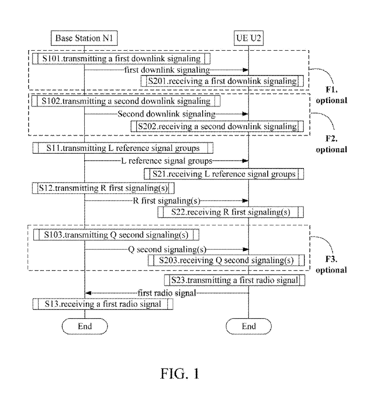
[0260]Embodiment 1 illustrates a flowchart of wireless transmission, as shown in FIG. 1. In FIG. 1, a base station N1 is a maintenance base station for a serving cell of a UE U2. In FIG. 1, steps in box F1, box F2 and box F3 are optional, respectively.
[0261]The base station N1 transmits a first downlink signaling in step S101; transmits a second downlink signaling in step S102; transmits L reference signal groups in S11; transmits R first signaling(s) in S12; transmits Q second signaling(s) in step S103; and receives a first radio signal in step S13.
[0262]The UE U2 receives a first downlink signaling in step S201; receives a second downlink signaling in step S202; receives L reference signal groups in step S21; receives R first signaling(s) in step S22; receives Q second signaling(s) in step S203; and transmits a first radio signal in step S23.
[0263]In Embodiment 1, the L reference signal groups are transmitted by L antenna port sets respectively, the R first signaling(s) is (are) r...
embodiment 2
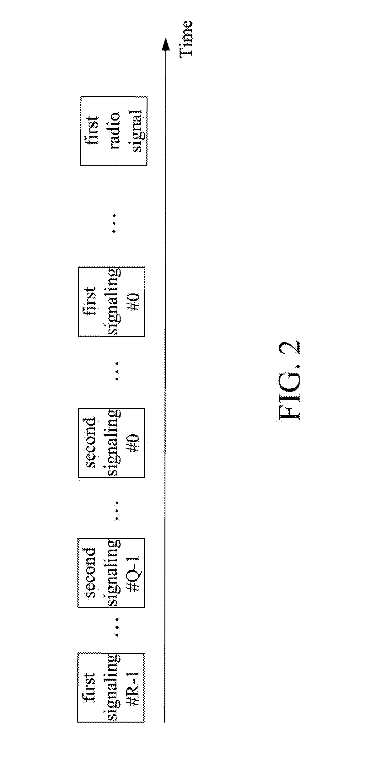
[0349]Embodiment 2 illustrates a timing diagram of R first signalings, Q second signalings and a first radio signal, as shown in FIG. 2. In FIG. 2, indices of the R first signaling(s) are #0, #1, #2 . . . , #R-1, respectively; indices of the Q second signaling(s) are #0, #1, #2 . . . , #Q-1, respectively.
[0350]In Embodiment 2, time domain resources occupied by any two first signalings of the R first signalings are orthogonal (i.e., non-overlapping); time domain resources occupied by any two first signalings of the Q second signalings are orthogonal (i.e., non-overlapping); a time domain resource occupied by the first radio signal is after a time domain resource occupied by a first signaling#0 and a time domain resource occupied by a second signaling#0.
[0351]In one embodiment, the R first signalings are dynamic signalings respectively.
[0352]In one embodiment, the R first signalings are dynamic signalings used for Uplink Grant respectively.
[0353]In one embodiment, the R first signalin...
embodiment 3
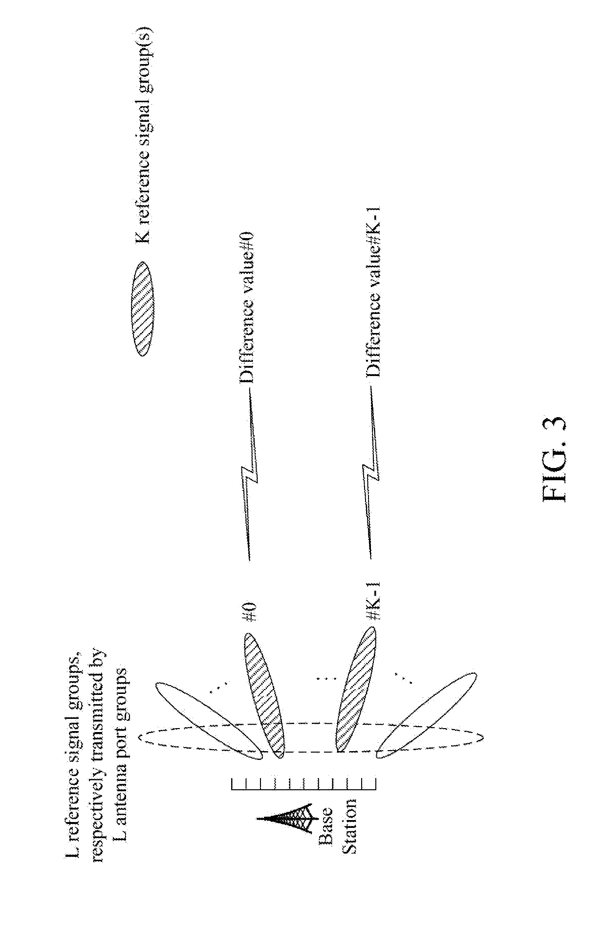
[0358]Embodiment 3 illustrates a schematic diagram of a relationship between K reference signal group(s) and K difference value(s), as shown in FIG. 3.
[0359]In Embodiment 3, L reference signal groups are transmitted by L antenna port sets respectively, the K reference signal group(s) is (are) a subset of the L reference signal groups. The K difference value(s) respectively corresponds(correspond) to K first reference power value(s). Measurement(s) on K reference signal group(s) is (are) respectively used for determining the K first reference power value(s). The L is a positive integer greater than 1, the K is a positive integer not greater than the L.
[0360]In one embodiment, the K first reference power value(s) is (are) linearly correlated to the K pathloss value(s) respectively, the K pathloss value(s) is (are) respectively determined by measurement(s) on the K reference signal group(s).
[0361]In one embodiment, a given reference signal group is one of the K reference signal group(s...
PUM
 Abstract
Description
Claims
Application Information
 - R&D
- Intellectual Property
- Life Sciences
- Materials
- Tech Scout
- Unparalleled Data Quality
- Higher Quality Content
- 60% Fewer Hallucinations
Browse by: Latest US Patents, China's latest patents, Technical Efficacy Thesaurus, Application Domain, Technology Topic, Popular Technical Reports.
© 2025 PatSnap. All rights reserved.Legal|Privacy policy|Modern Slavery Act Transparency Statement|Sitemap|About US| Contact US: help@patsnap.com


