
B1 field map with contrast medium injection

a field map and contrast medium technology, applied in the field of b1 field map with contrast medium injection, can solve the problems of shortened t1 time and inability to determine b1 accurately, and achieve the effect of accurate outer contours of the person under examination

Pending Publication Date: 2019-11-07
SIEMENS HEATHCARE GMBH
View PDF10 Cites 0 Cited by
  • Summary
  • Abstract
  • Description
  • Claims
  • Application Information

AI Technical Summary

Benefits of technology

The present disclosure allows for the accurate determination of the position of a person under examination during a medical imaging scan. This is possible by using MR profile scans that provide information about the person's position and edges. Additionally, the position of the person before the injection of a contrast medium can be calculated using the B1 field map calculated before the contrast medium is administered. These techniques allow for a faster and more accurate determination of the person's position during the medical imaging scan.

Problems solved by technology

If, however, the scans involve contrast medium, the T1 time is shortened at certain locations such that a B1 determination is no longer possible.

Method used


Image

  • B1 field map with contrast medium injection
  • B1 field map with contrast medium injection

Examples


Embodiment Construction

[0027]The present disclosure will now be described in greater detail based on certain embodiments, referring to the accompanying drawings. In the drawings, the same reference signs denote the same or similar elements. Furthermore, the drawings are schematic representations of different embodiments of the disclosure and the elements shown in the figures are not necessarily shown to scale. Rather, the elements shown in the drawings are reproduced so that their function and purpose are comprehensible to a person skilled in the art. The connections shown in the figures between the functional units or other elements may also be implemented as an indirect connection, whereby a connection may be wireless or wire-connected. Functional units may be implemented as hardware, software or a combination of hardware and software.

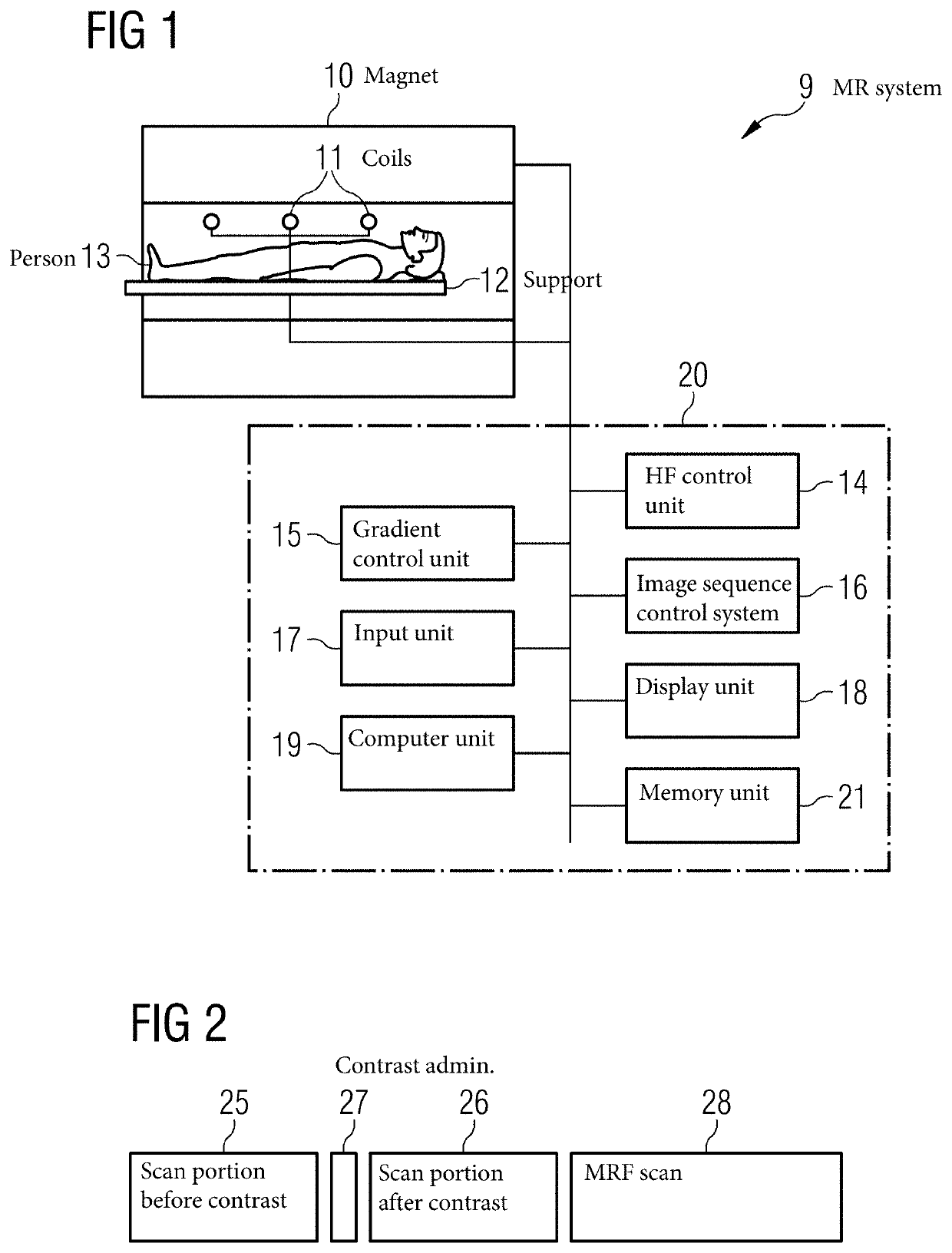
[0028]Shown schematically in FIG. 1 is a MR system with which, as described below, MR images of a person under examination 13 may be recorded, with contrast medium adminis...


PUM


Abstract

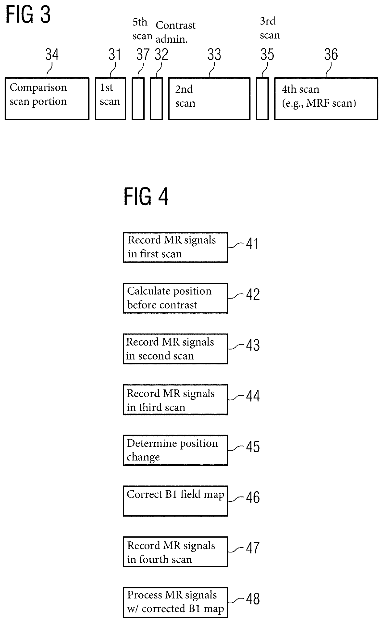
A method is provided for determining a movement-corrected B1 field map on contrast medium injection, wherein before the injection, a B1 field map is determined. Following the contrast medium administration, a position change is determined at the position at which the B1 field map was determined. With the position change and the B1 field map, the movement-corrected B1 field map is determined.

Description

[0001]The present patent document claims the benefit of German Patent Application No. DE 10 2018 206 950.6, filed May 4, 2018, which is also hereby incorporated by reference.TECHNICAL FIELD[0002]The disclosure relates to a method for recording magnetic resonance (MR) signals from a person under examination in a MR system while contrast medium is injected into a person under examination. The associated MR system, which is configured to carry out the method, is also provided. In addition, a computer program and an electronically readable data carrier are provided.BACKGROUND[0003]Magnetic resonance fingerprinting (MRF) is a technology for operating quantitative imaging by MR systems. Exemplary MRF methods are described in the following publications: U.S. Patent Application Publication No. 2017 / 0322276 A1, U.S. Patent Application Publication No. 2017 / 0115368 A1, U.S. Patent Application Publication No. 2018 / 0003787 A1, U.S. Patent Application Publication No. 2016 / 0259022 A1, U.S. Patent ...

Claims


Application Information

Patent Timeline
IPC IPC(8): A61B5/00A61B5/055G01R33/56G01R33/483
CPCG01R33/4831A61B5/7207G01R33/5601A61B5/055G01R33/56509G01R33/246
Inventor KARTÄUSCH, RALF
Owner SIEMENS HEATHCARE GMBH
Learn More